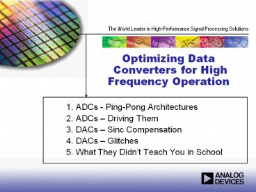
ADCs - Ping-Pong Architectures - PowerPoint PPT Presentation
Title:
ADCs - Ping-Pong Architectures
Description:
Optimizing Data Converters for High Frequency Operation ADCs - Ping-Pong Architectures ADCs Driving Them DACs Sinc Compensation DACs Glitches – PowerPoint PPT presentation
Number of Views:278
Avg rating:3.0/5.0
Title: ADCs - Ping-Pong Architectures
1
Optimizing Data Converters for High Frequency
Operation
- ADCs - Ping-Pong Architectures
- ADCs Driving Them
- DACs Sinc Compensation
- DACs Glitches
- What They Didnt Teach You in School
2
Ping Pong ADCsReferences
- Analog Dialogue 37-8 (August 2003)
- Analog Dialogue 39-5 (May 2005)
- http//www.v-corp.com/
- Do a Patent Search on Inventor Velazquez
Classification 341/118
3
Nyquist Theorem Limits Frequency Bandwidth
4
Ping-Pong ADCSArchitecture
5
Ping-Pong ADCSRaw Spectral Response
6
Ping-Pong ADCSMatching Requirements
Performance Requirement at 180 MHz SFDR (dBc) Gain Matching () Aperture Matching (fsec)
12 Bits 74 .04 0
12 Bits 74 0 350
12 Bits 74 .02 300
14 Bits 86 .01 0
14 Bits 86 0 88
14 Bits 86 .005 77
7
Advanced Filter Bank (AFB)Reduces Spurs Due to
ADC Mismatch
8
Ping Pong ADCsTrimmed SFDR
9
Ping Pong ADCsTemperature Effects
10
Linear Error Compensation (LinComp)Corrects for
Non-Linearities
11
Driving ADCsReferences
- Analog Dialogue 39-4 (April 2005)
- Analog-Digital Conversion Seminar (2004)
12
Transformer Coupling Gives Best High Frequency
Performance
13
ADC Drive
14
Dual Transformers Improve Balance at High
Frequencies
15
Baluns Have a Wider Frequency Response
16
Applying Voltage Gain Can Improve Noise
Performance
17
DACsSome Things You May Not Have Thought Of
- Sinc Compensation Effects
- Glitch Energy
18
DACs Suffer From Sinc Response
dB
Frequency (xFs)
19
Use Sinc Compensation to Reduce Passband Droop
dB
Frequency (xFs)
20
Passband is Flat But There is 3.5 dB Insertion
Loss
dB
Frequency (xFs)
21
Sinc Compensation Doesnt Work So Wellat Super
Nyquist Bands
dB
Frequency (xFs)
22
AD9779 Vs AD9777 Time Domain Plot
Both DACs synthesizing a 1MHz sine wave in 1x
interpolation mode with a 160MSPS clock rate.
Due to the unique output stage of the AD9779, its
time domain waveform has much more glitch energy
than the AD9777
AD9777
AD9779
23
Glitches Are Worsebut Noise Floor is Better
24
Glitches Are Worsebut 3rd Order IMD Is better
25
Things They Dont Teach You In School
- Watch ALL your inputs
- Proper Decoupling
- Differential Signaling
- Clean Your Clock
26
How many Inputs Does a Data Converter Really Have?
A
D
D
A
A
VD
VA
CSTRAY
"QUIET DIGITAL
NOISY DATA BUS
Analog I/O
BUFFER LATCH
ANALOG CIRCUITS
DIGITAL CIRCUITS
B
Clock
A
CSTRAY
ID
IA
Reference
AGND
DGND
A
D
V
D
A
A
DIGITAL GROUND PLANE
ANALOG GROUND PLANE
A
D
27
Power Supply Decoupling Must Be Effective at Very
High Frequencies
28
Why Differential Signaling?
29
How Clean Does Your Clock Need To Be
1000
1000
SNR 1.76dB
ENOB
300
300
4
6.02
100
6
100
tj
tj
8
30
30
(ps)
(ps)
10
10
10
12
3
3
14
1
1
PLL WITH VCO
16
0.3
0.3
18
PLL WITH VCXO
0.1
0.1
DEDICATED LOW NOISE XTAL OSC
0.03
0.03
1
10
100
1000
3
30
300
FULL-SCALE ANALOG INPUT FREQUENCY (MHz)
30
In Conclusion
- Hopefully you learned something
- Getting good high-frequency performance is tough
- But there are some things you can do to get the
best performance you can - Thank you for your kind attention
- Please talk to you friendly local ADI Sales
Engineer when youre ready to start your next
design


