

We're ready to look at an implementation of the MIPS PowerPoint PPT Presentation
Title: We're ready to look at an implementation of the MIPS
1
Chapter 5The Processor Datapath Control
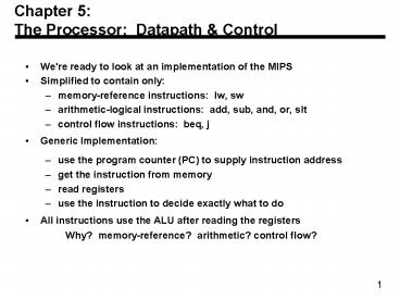
- We're ready to look at an implementation of the
MIPS - Simplified to contain only
- memory-reference instructions lw, sw
- arithmetic-logical instructions add, sub, and,
or, slt - control flow instructions beq, j
- Generic Implementation
- use the program counter (PC) to supply
instruction address - get the instruction from memory
- read registers
- use the instruction to decide exactly what to do
- All instructions use the ALU after reading the
registers Why? memory-reference? arithmetic?
control flow?
2
More Implementation Details
- Abstract / Simplified ViewTwo types
of functional units - elements that operate on data values
(combinational) - elements that contain state (sequential)
3
State Elements
- Unclocked vs. Clocked
- Clocks used in synchronous logic
- when should an element that contains state be
updated?
4
An unclocked state element
- The set-reset latch
- output depends on present inputs and also on past
inputs
5
Latches and Flip-flops
- Output is equal to the stored value inside the
element (don't need to ask for permission to
look at the value) - Change of state (value) is based on the clock
- Latches whenever the inputs change, and the
clock is asserted - Flip-flop state changes only on a clock
edge (edge-triggered methodology)
"logically true", could mean electrically low
A clocking methodology defines when signals can
be read and written wouldn't want to read a
signal at the same time it was being written
6
D-latch
- Two inputs
- the data value to be stored (D)
- the clock signal (C) indicating when to read
store D - Two outputs
- the value of the internal state (Q) and it's
complement
7
D flip-flop
- Output changes only on the clock edge
8
Our Implementation
- An edge triggered methodology
- Typical execution
- read contents of some state elements,
- send values through some combinational logic
- write results to one or more state elements
9
Register File
- Built using D flip-flops
10
Register File
- Note we still use the real clock to determine
when to write
11
Simple Implementation
- Include the functional units we need for each
instruction
Why do we need this stuff?
12
Building the Datapath
- Use multiplexors to stitch them together
13
Control
- Selecting the operations to perform (ALU,
read/write, etc.) - Controlling the flow of data (multiplexor inputs)
- Information comes from the 32 bits of the
instruction - Example add 8, 17, 18 Instruction
Format 000000 10001 10010 01000
00000 100000 op rs rt rd shamt
funct - ALU's operation based on instruction type and
function code
14
Control
- e.g., what should the ALU do with this
instruction - Example lw 1, 100(2) 35 2 1
100 op rs rt 16 bit offset - ALU control input 000 AND 001 OR 010 add 110
subtract 111 set-on-less-than - Why is the code for subtract 110 and not 011?
15
Control
- Must describe hardware to compute 3-bit ALU
control input - given instruction type 00 lw, sw 01 beq,
11 arithmetic - function code for arithmetic
- Describe it using a truth table (can turn into
gates)
16
Control
17
Control
- Simple combinational logic (truth tables)
18
Our Simple Control Structure
- All of the logic is combinational
- We wait for everything to settle down, and the
right thing to be done - ALU might not produce right answer right away
- we use write signals along with clock to
determine when to write - Cycle time determined by length of the longest
path
We are ignoring some details like setup and hold
times
19
Single Cycle Implementation
- Calculate cycle time assuming negligible delays
except - memory (2ns), ALU and adders (2ns), register file
access (1ns)
20
Where we are headed
- Single Cycle Problems
- what if we had a more complicated instruction
like floating point? - wasteful of area
- One Solution
- use a smaller cycle time
- have different instructions take different
numbers of cycles - a multicycle datapath
21
Multicycle Approach
- We will be reusing functional units
- ALU used to compute address and to increment PC
- Memory used for instruction and data
- Our control signals will not be determined solely
by instruction - e.g., what should the ALU do for a subtract
instruction? - Well use a finite state machine for control
22
Review finite state machines
- Finite state machines
- a set of states and
- next state function (determined by current state
and the input) - output function (determined by current state and
possibly input) - Well use a Moore machine (output based only on
current state)
23
Review finite state machines
- Example
- B.21 A friend would like you to build an
electronic eye for use as a fake security
device. The device consists of three lights
lined up in a row, controlled by the outputs
Left, Middle, and Right, which if asserted,
indicate that a light should be on. Only one
light is on at a time, and the light moves from
left to right and then from right to left, thus
scaring away thieves who believe that the device
is monitoring their activity. Draw the graphical
representation for the finite state machine used
to specify the electronic eye. Note that the
rate of the eyes movement will be controlled by
the clock speed (which should not be too great)
and that there are essentially no inputs.
24
Multicycle Approach
- Break up the instructions into steps, each step
takes a cycle - balance the amount of work to be done
- restrict each cycle to use only one major
functional unit - At the end of a cycle
- store values for use in later cycles (easiest
thing to do) - introduce additional internal registers
25
Five Execution Steps
- Instruction Fetch
- Instruction Decode and Register Fetch
- Execution, Memory Address Computation, or Branch
Completion - Memory Access or R-type instruction completion
- Write-back step INSTRUCTIONS TAKE FROM 3 - 5
CYCLES!
26
Step 1 Instruction Fetch
- Use PC to get instruction and put it in the
Instruction Register. - Increment the PC by 4 and put the result back in
the PC. - Can be described succinctly using RTL
"Register-Transfer Language" IR
MemoryPC PC PC 4Can we figure out the
values of the control signals?What is the
advantage of updating the PC now?
27
Step 2 Instruction Decode and Register Fetch
- Read registers rs and rt in case we need them
- Compute the branch address in case the
instruction is a branch - RTL A RegIR25-21 B
RegIR20-16 ALUOut PC (sign-extend(IR15-
0) ltlt 2) - We aren't setting any control lines based on the
instruction type (we are busy "decoding" it in
our control logic)
28
Step 3 (instruction dependent)
- ALU is performing one of three functions, based
on instruction type - Memory Reference ALUOut A
sign-extend(IR15-0) - R-type ALUOut A op B
- Branch if (AB) PC ALUOut
29
Step 4 (R-type or memory-access)
- Loads and stores access memory MDR
MemoryALUOut or MemoryALUOut B - R-type instructions finish RegIR15-11
ALUOutThe write actually takes place at the
end of the cycle on the edge
30
Write-back step
- RegIR20-16 MDR
- What about all the other instructions?
31
Summary
32
Simple Questions
- How many cycles will it take to execute this
code? lw t2, 0(t3) lw t3, 4(t3) beq
t2, t3, Label assume not add t5, t2,
t3 sw t5, 8(t3)Label ... - What is going on during the 8th cycle of
execution? - In what cycle does the actual addition of t2 and
t3 takes place?
33
Implementing the Control
- Value of control signals is dependent upon
- what instruction is being executed
- which step is being performed
- Use the information weve acculumated to specify
a finite state machine - specify the finite state machine graphically, or
- use microprogramming
- Implementation can be derived from specification
34
Graphical Specification of FSM
- How many state bits will we need?
35
Finite State Machine for Control
- Implementation
36
PLA Implementation
- If I picked a horizontal or vertical line could
you explain it?
37
ROM Implementation
- ROM "Read Only Memory"
- values of memory locations are fixed ahead of
time - A ROM can be used to implement a truth table
- if the address is m-bits, we can address 2m
entries in the ROM. - our outputs are the bits of data that the address
points to.m is the "heigth", and n is
the "width"
0 0 0 0 0 1 1 0 0 1 1 1 0 0 0 1 0 1 1 0 0 0 1 1 1
0 0 0 1 0 0 0 0 0 0 1 0 1 0 0 0 1 1 1 0 0 1 1
0 1 1 1 0 1 1 1
38
ROM Implementation
- How many inputs are there? 6 bits for opcode, 4
bits for state 10 address lines (i.e., 210
1024 different addresses) - How many outputs are there? 16 datapath-control
outputs, 4 state bits 20 outputs - ROM is 210 x 20 20K bits (and a rather
unusual size) - Rather wasteful, since for lots of the entries,
the outputs are the same i.e., opcode is often
ignored
39
ROM vs PLA
- Break up the table into two parts 4 state bits
tell you the 16 outputs, 24 x 16 bits of
ROM 10 bits tell you the 4 next state bits,
210 x 4 bits of ROM Total 4.3K bits of ROM - PLA is much smaller can share product terms
only need entries that produce an active
output can take into account don't cares - Size is (inputs ? product-terms) (outputs ?
product-terms) For this example
(10x17)(20x17) 460 PLA cells - PLA cells usually about the size of a ROM cell
(slightly bigger)
40
Another Implementation Style
- Complex instructions the "next state" is often
current state 1
41
Details
42
Microprogramming
- What are the microinstructions ?
43
Microprogramming
- A specification methodology
- appropriate if hundreds of opcodes, modes,
cycles, etc. - signals specified symbolically using
microinstructions - Will two implementations of the same architecture
have the same microcode? - What would a microassembler do?
44
Microinstruction format
45
Maximally vs. Minimally Encoded
- No encoding
- 1 bit for each datapath operation
- faster, requires more memory (logic)
- used for Vax 780 an astonishing 400K of memory!
- Lots of encoding
- send the microinstructions through logic to get
control signals - uses less memory, slower
- Historical context of CISC
- Too much logic to put on a single chip with
everything else - Use a ROM (or even RAM) to hold the microcode
- Its easy to add new instructions
46
Microcode Trade-offs
- Distinction between specification and
implementation is sometimes blurred - Specification Advantages
- Easy to design and write
- Design architecture and microcode in parallel
- Implementation (off-chip ROM) Advantages
- Easy to change since values are in memory
- Can emulate other architectures
- Can make use of internal registers
- Implementation Disadvantages, SLOWER now that
- Control is implemented on same chip as processor
- ROM is no longer faster than RAM
- No need to go back and make changes
47
The Big Picture
Recommended

