LARGE-SIGNAL BEHAVIOR OF BJTS - PowerPoint PPT Presentation
1 / 20
Title:
LARGE-SIGNAL BEHAVIOR OF BJTS
Description:
... NPN Bipolar Junction Transistor Carrier Transport in a BJT BJT Band Diagram BJT Current Equations Forward-Active Region of a BJT Forward-Active Region of a ... – PowerPoint PPT presentation
Number of Views:292
Avg rating:3.0/5.0
Title: LARGE-SIGNAL BEHAVIOR OF BJTS
1
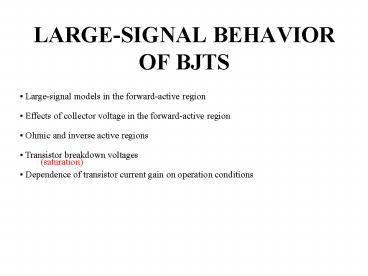
LARGE-SIGNAL BEHAVIOR OF BJTS
- Large-signal models in the forward-active region
- Effects of collector voltage in the
forward-active region - Ohmic and inverse active regions
- Transistor breakdown voltages
- Dependence of transistor current gain on
operation conditions
(saturation)
2
Bipolar Junction Transistor (BJT)
One diode...
Why not another diode
3
Bipolar Junction Transistor (BJT)
What happens when we combine them?
4
NPN Bipolar Junction Transistor
Emitter (E)
Collector (C)
Base (B)
BJT Bipolar Junction Transistor
5
Carrier Transport in a BJT
6
BJT Band Diagram
Forward-Active Region of Operation
Base
Collector
Emitter
Base Width (W)
Ef
7
BJT Current Equations
Base Width (W)
No recombination
Electrons and Holes recombine in the base region
at a rate t.
Recombination
Typically, b is limited by this recombination
(looks like a saturated subthreshold MOSFET)
8
Forward-Active Region of a BJT
Carrier Concentration
E-B Depletion Region
C-B Depletion Region
0
W
Emitter
Base
Collector
VBE gt 0 (Forward Biased), VBC lt 0 (Reversed
Biased)
9
Forward-Active Region of a BJT
Carrier Concentration
E-B Depletion Region
C-B Depletion Region
0
W
Emitter
Base
Collector
W ltlt Ln
10
Gummel Plots
-5
Ic n1, Is 5.52fA
10
-6
10
Currents
-7
10
-8
10
-9
10
Ib n1.019, Is 0.048fA
-10
10
-11
10
-12
10
0.1
0.2
0.3
0.4
0.5
0.6
0.7
Base-Emitter Voltage (V)
11
Gummel Plot b depends on Ic
12
Current gain changes
Region I Low current region where bF
decreases as iC decreases
Region II Midcurrent region where bF is
approximately constant
Region III High current region where bF
decreases as iC increases
13
Large-Signal Modeling (sort of)
Does not incorporate the Early effect
14
Reverse-Active Region of a BJT
Carrier Concentration
E-B Depletion Region
C-B Depletion Region
0
W
Emitter
Base
Collector
VBC gt 0 (Forward Biased), VBE lt 0 (Reversed
Biased)
15
Ohmic Region of a BJT
Carrier Concentration
E-B Depletion Region
C-B Depletion Region
0
W
Emitter
Base
Collector
VBC gt 0 (Forward Biased), VBE gt 0 (Forward
Biased)
This region is often called saturation
16
Ebers-Moll Model of a BJT
Carrier Concentration
E-B Depletion Region
C-B Depletion Region
0
W
Emitter
Base
Collector
VBE/UT
VBC/UT
IC IC0 ( e - 1 ) - IE0 ( e -
1 ) IC0 e ( ( e - (IE0
/ IC0) e ) IC0 - IE0
VB/UT
-VE/UT
-Vc/UT
17
Ohmic and Active BJT Regions
5
4.5
4
VBE/UT
IC (IC0 - IE0 ) IC0 e (
1 - (IE0 / aR IC0) e )
3.5
-VCE/UT
3
2.5
Collector current (mA)
2
1.5
1
0.5
0
0
0.5
1
1.5
2
2.5
3
3.5
4
4.5
5
Collector voltage (V)
18
Simplified Ohmic Model
In ohmic, both junctions are forward biased
and the impedance levels looking into
the emitter or collector is very low.
VBE(on) 0.6 to 0.7V and VCE(sat) 0.2V
19
TRANSISTOR BREAKDOWN VOLTAGES
Common-Base Transistor Breakdown Characteristics
20
BJT Breakdown Characteristics


