Basic Microcomputer Design - PowerPoint PPT Presentation
1 / 18
Title:
Basic Microcomputer Design
Description:
Title: Basic Microcomputer Design Author: jane Last modified by: jane Created Date: 8/26/2002 5:25:42 AM Document presentation format: On-screen Show – PowerPoint PPT presentation
Number of Views:258
Avg rating:3.0/5.0
Title: Basic Microcomputer Design
1
Basic Microcomputer Design
2
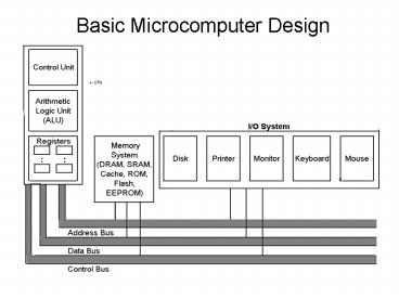
Inside the CPU
- Registers storage locations
- Control Unit (CU) coordinates the sequencing of
steps involved in executing machine instructions - Arithmetic Logic Unit (ALU) - performs arithmetic
and logical operations - Clock synchronizes the internal operations of
the CPU with the other system components
3
Bus Structure
- Bus - a group of parallel wires that transfer
information from one part of the computer to
another. - Control Bus synchronizes the actions of all of
the devices attached to the system bus. - Address Bus passes the addresses of
instructions and data between the CPU and memory
(or I/O). - Data Bus transfers instructions and data
between the CPU and memory (or I/O).
4
Bus Sizes
- For the 8086 Processor
- Data Bus 16 bits (16-bit processor)
- Address Bus 20 bits (can access 1M of memory)
5
(No Transcript)
6
The Intel CPU Family
7
Notes from Intel Family Chart
- Notice that 386 Pentium 4 are 32-bit processors
(32-bit data bus 4 bytes) - Notice that 386 and beyond have 32-bit address
bus can access (4G of memory addresses).
8
Machine Cycle
- Most basic unit of time for machine instructions
- the time required for one complete clock cycle.
- Machine instructions require at least 1 clock
cycle to execute. Most require more. - Wait states empty clock cycles of machine
execution time (due to memory access time being
slower than speed of clock).
9
Instruction Execution Cycle
- If using Memory operand (mov ax, 0A69Bh)
- Calculate address of operand
- Place address of operand on address bus
- Wait for memory to get operand and pass it on
- data bus
10
(No Transcript)
11
Instruction Cycle
- Fetch
- Decode
- Fetch memory operands
- Execute
- Store output operand
12
Pipelining Versus Non-Pipelining
- In non-pipelined systems, for k execution states,
n instructions require (nk) cycles to process. - Using a pipelined system with k execution
states, n instructions require (k (n-1)) cycles
to complete.
13
Pipeline for 8086 (2-stage pipelining)
14
2-stage Pipelining
- Bus Interface Unit accesses memory and provides
I/O - Execution Unit executes the microcode
instructions.
15
IA-32 Processor Pipelinig(6-stage Pipelining)
- Bus Interface Unit accesses memory and provides
I/O - Code Prefetch Unit receives instructions from
the BIU and inserts them into a holding area
(instruction queue) - Instruction Decode Unit decodes machine
instructions from the prefetch queue and
translates them into microcode. - Execution Unit executes the microcode
instructions. - Segment Unit translates logical addresses into
linear addresses and performs protection checks - Paging Unit translates linear addresses into
physical addresses, performs page protection
checks and keeps a list of recently accessed
pages
16
Superscalar Architecture
- Processors that allow two or more execution
pipelines (two or more instructions can be in the
execution stages at the same time).
17
Reading from memory
- Typically the CPU clock is running much faster
than memory access time. - Cache
- 1st Level on chip
- 2nd Level separate high speed RAM
18
(No Transcript)

