
Design of a Simulink 2-DOF Robot Arm Control Workstation PowerPoint PPT Presentation
1 / 22
Title: Design of a Simulink 2-DOF Robot Arm Control Workstation
1
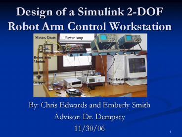
Design of a Simulink 2-DOF Robot Arm Control
Workstation
- By Chris Edwards and Emberly Smith
- Advisor Dr. Dempsey
- 11/30/06
2
Presentation Outline
- Project Summary
- Previous Work
- Functional Description
- Functional Requirements and Specifications
- Overall Block Diagram
- Subsystems
- Progress
- Project Schedule
- Equipment and Parts List
- Questions and Discussion
3
Project Summary
- 2-DOF robot arm control __workstation
- Designed in Simulink __environment
- Mimics Quanser workstation
- Controller design
4
Workstation Design User GUI
5
Previous Work
- Vaccari and Osterholts Project Achievements
- Modeling the robot arm in SimMechanics Toolbox
- Designing closed-loop controllers
- Real time visualization using the Virtual Reality
__Toolbox - Implementing force feedback joystick control
- Note Non-inverting configuration was used with
no load.
6
Workstation Design VR Modeling
7
Modeling Springs
- The new system will include a separate model for
the springs allowing another degree of freedom.
This will treat the robot arm and base as
separate entities.
8
Primary Project Goals
- Add rotary flexible joint to the existing system
model - Validate new model through experimental results
- System ID for designing controllers
- Design closed-loop controllers for 2-DOF robot
arm - Single-loop position controller
- Double-loop position/velocity controller
- Feed-forward controller
9
Secondary Project Goals
- Design advanced controller for the 2-DOF robot
arm - Investigate different robot arm configurations
- Level
- Inverted
- Non-inverted
- Make additions to previous virtual reality
workstation
10
Functional Description
- Mass-Damper-Spring System
- Mass
- Arm
- Gripper
- Load
- Damper
- Friction will act as the damper
- Spring
- Springs attach the robot arm to the base
11
Mechanical Specifications
Mechanical System
Position Accuracy 2
Velocity Accuracy 5/sec
O.S. 5
Ts 2 sec
Tp 1 sec
Phase Margin (PM) 50
Gain Margin (GM) 4
12
Controller Calculation Times
Controllers Controllers Calculation Time
1 Proportional (P) Controller Proportional Derivative (PD) Controller Proportional Integral Derivative (PID) Controller lt 500µs
2 PID-Type with Feed Forward (F.F.) Control lt 800µs
3 Type-2 Controller with Velocity Control Loop lt 1 ms
4 Type-2 Controller with Torque Control Loop lt 1 ms
5 Type-3 and 4 Controllers Combined lt 1.1 ms
6 Advanced Control State-Variable Control Disturbance Rejection Control lt 2 ms
13
Presentation Outline
- Project Summary
- Previous Work
- Functional Description
- Functional Requirements and Specifications
- Overall Block Diagram
- Subsystems
- Progress
- Project Schedule
- Equipment and Parts List
- Questions and Discussion
14
Overall Block Diagram
15
Plant Subsystem
16
Position Controller
17
Position/Velocity Controller
18
FF/Position/Velocity Controller
19
Progress
- SimMechanics Tutorial
- Proportional Controller Design (Pendulum
- Configuration)
- Test Controller
- Quanser Tutorial
20
Project Schedule
Weeks Chris Edwards Emberly Smith
1-3 SimMechanics Model GUI Design
4-5 System ID of Level-Arm System and Model Validation System ID of Level-Arm System and Model Validation
6 Velocity/Position Controller Feed-Forward Controller
7 FF/Velocity/Position Controller Notch Filter Design
8 Load Testing and Add Joystick to Quanser System Load Testing and Add Joystick to Quanser System
9 Modify Virtual Reality Workstation Modify Virtual Reality Workstation
10-12 Advanced Controller and Other Arm Configurations Advanced Controller and Other Arm Configurations
13-14 Final Preparations Reports, Presentation, EXPO, etc. Final Preparations Reports, Presentation, EXPO, etc.
21
Equipment and Parts List
- Quanser Workstation
- Wingman Attack 2 Joystick
- Software
- SimMechanics
- Simulink
- Virtual Reality Toolbox
22
Questions?
Recommended
