
Wind Tunnels PowerPoint PPT Presentation
Title: Wind Tunnels
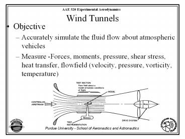
1
Wind Tunnels
- Objective
- Accurately simulate the fluid flow about
atmospheric vehicles - Measure -Forces, moments, pressure, shear stress,
heat transfer, flowfield (velocity, pressure,
vorticity, temperature)
2
Low Speed Vehicles - Mlt.3
Gallilean Transformation
Flight in atmosphere Scale L
Wind Tunnel - Model Scale
Issues Flow Quality - Uniformity
and Turbulence Level
Wind Tunnel Wall Interference Reynolds
Number Simulation
Stationary Walls
3
Reynolds Number Scaling
- Most important on vehicles with partial laminar
flow. The transition is very sensitive to
Reynolds Number - Use trip stripsor roughness to cause boundary
layer transition on the model at the same
location as on the full scale vehicle
4
Transonic Regime .7ltMlt1.2
- Must Match Reynolds Number and Mach Number
Must change fluid density and viscosity to match
Re and M Cryogenic Wind Tunnels are designed for
this reason
5
HistoryWhirling Arm
6
Eiffel Tunnel
7
Wright Brothers
8
(No Transcript)
9
Wind Tunnel Layout
- Closed Return
- Open Return
- Double Return
- Annular Return
10
Closed Return(open test section)
11
Open ReturnClosed Test Section
12
Double Return
U N I V E R S I T Y OF W A S H I N G T O N A E
R O N A U T I C A L L A B O R A T O R Y Kirsten
Wind Tunnel
13
Annular Wind Tunnel
14
Types of Wind Tunnels
- Subsonic
- Transonic
- Supersonic
- Hypersonic
- Cryogenic
- Specialty
- Automobiles
- Environmental- Icing, Buildings, etc.
15
Subsonic Wind Tunnels
16
40 x 80 and 80 x 120 NASA Ames
17
40- by 80- Foot Wind Tunnel Specifications Primar
y Use The facility is used primarily for
large-scale or full-scale testing of aircraft and
rotorcraft, including high-lift and noise
suppression development for subsonic and high
speed transports, powered lift, high
angle-of-attack for fighter aircraft and
propulsion systems Capability Mach Number
0-0.45 Reynolds Number per foot 3 X 10⁶
Stagnation Pressure Atmospheric Temperature
Range 485 - 580 R Closed circuit, single
return, continuous flow, closed throat wind
tunnel with low turbulence Model-support
systems available include a 3 strut arrangement
with a nose or tail variable height strut, a
semi-span mount and a sting The entire model
support can be yawed a total of 290 Six
components of force and moment are measured by
the mechanical, external balance under the test
section, or by internal strain-gage balances in
the sting or rotor testbeds Test section walls
are lined with a 10" acoustic lining, and the
floor and ceiling have a 6" acoustic lining
80- by 120- Foot Wind Tunnel Specifications Prima
ry Use The facility is used primarily for
large-scale or full-scale testing of aircraft and
rotorcraft, including high-lift development for
subsonic transports, V/STOL powered lift, high
angle-of-attack for fighter aircraft and
propulsion systems Capability Mach Number
0-0.15 Reynolds Number per foot 1.2 X 10⁶
Stagnation Pressure Atmospheric
Temperature Range 485 - 580 R Indraft,
continuous flow, closed throat wind tunnel
18
Fans for 40x80 and 80x120
19
80x120
40x80
20
12 foot Pressure Tunnel
21
(No Transcript)
22
12-Foot Pressure Wind Tunnel
Specifications Primary Use The facility is
used primarily for high Reynolds number testing,
including the development of high-lift systems
for commercial transports and military aircraft,
high angle-of-attack testing of maneuvering
aircraft, and high Reynolds number research.
Capability Mach Number 0-0.52
Reynolds Number per foot 0.1 - 12X106
Stagnation Pressure, PSIA 2.0 - 90
Temperature Range 540 - 610 R Closed
circuit, single return, variable density, closed
throat, wind tunnel with exceptionally low
turbulence Model-support systems available
Strut with variable pitch and roll
capability High angle-of-attack
turntable system Dual-strut turntable
mechanism for high-lift testing
Semispan mounting system Internal
strain-gage balances used for force and moment
testing Capability for measuring multiple
fluctuating pressures Temperature-controlled
auxiliary high-pressure (3000 psi)
23
(No Transcript)
24
(No Transcript)
25
TransonicWind Tunnels
26
Transonic Wind Tunnels
Wall interference is a severe problem for
transonic wind tunnels. Flow can choke
Shock wave across the tunnel test
section Two Solutions Porous Walls
Movable Adaptive Walls
27
(No Transcript)
28
The 8x6/9x15 Complex at the NASA Lewis Research
Center in Cleveland, Ohio is, is unique in its
dual capacity role as both a high-speed and low
speed test facility. 8x6 Functions
Capabilities The 8x6 Foot Supersonic Wind Tunnel
provides customers with a Facility capable of
testing large scale aeropropulsion hardware
In a continuous Mach 0-2.0 airstream At
varying Reynolds Numbers (3.6 - 4.8 x 10⁶/ft) and
altitude conditions (ambient to 38,000ft)
In either aerodynamic (closed) or Propulsion
(open) cycle without exhaust scoops
Employing high data systems to support steady and
transient data acquisition Supported by a
variety of systems including Schlieren, infrared
imaging, sheet lasers, LDV, GH2 fuel, high
pressure air, and hydraulics.
8x6 Characteristics Performance
Test section size 8ft H, 6ft W,
23.5ft L Mach number range
0 - 2.0 Relative altitude
1000 - 35000 ft Dynamic Pressure
3.6 - 4.8 x 10⁶/ft
Stagnation Pressure 15.3 - 25 psia
Temperature 60 - 250oF
29
8x6 at NASA Lewis
30
9x15 at NASA Lewis Back Leg of the 8x6
31
Modane-Avrieux
S1MA Wind Tunnel Atmospheric, closed-circuit,
continuous flow wind tunnel, from Mach 0.05 to
Mach 1
S1MA wind tunnel is equipped with two
counterrotating fans, driven by Pelton turbines,
the power of which is 88 MW Mach number is
continuously adjustable from 0.05 to 1 by varying
the fan speed from 25 to 212 rpm.
32
16T at AEDC
33
S2Ma Wind Tunnel
34
Supersonic Wind Tunnels
35
(No Transcript)
36
(No Transcript)
37
(No Transcript)
38
Hypersonic Wind Tunnels
39
(No Transcript)
40
Principle Operation Detonation Driven Shock
Tunnel Set- up and wave plan
Initial conditions low pressure section test
gas air, about 25 kPa for tailored cond. deton.
section oxyhydrogen- helium/ argon mixtures,
max. 7 MPa damping section expansion volume
low initial pressures
41
(No Transcript)
42
(No Transcript)
43
The NASA Langley 8-Foot High Temperature Tunnel
(8 HTT)
enables the testing of large hypersonic airbreathi
ng propulsion systems at flight enthalpies
from Mach 4 to Mach 7.
44
Hypersonic Shock Tunnels at Calspan
The performance chart shows that the high
enthalpy 96-inch tunnel is capable of
simultaneously duplicating velocity (total
enthalpy) and density altitude over a wide range
of hypersonic flight conditions. These test
conditions cover the widest range of any in the
country.
45
(No Transcript)
46
(No Transcript)
47
(No Transcript)
48
CryogenicWind Tunnels
49
(No Transcript)
50
NATIONAL TRANSONIC FACILITY
51
(No Transcript)
52
(No Transcript)
53
The Cryogenic Ludwieg-Tube at Göttingen (KRG)
Adaptive wall test section
54
AutomobileWind Tunnels
55
(No Transcript)
56
(No Transcript)
57
IcingWind Tunnels
58
Icing Tunnel NASA Lewis Research Center
59
(No Transcript)
60
AutomobileWind Tunnels
61
(No Transcript)
62
(No Transcript)
63
Wind Tunnel Power Requirements
64
Energy Ratio
Subscript 0 refers to the test section P is the
motor power
is the fan efficiency
65
Wind Tunnel Circuit Elements
66
Losses
Local Pressure Loss Coefficient
Pressure Loss Referred to Test Section
Section Energy Loss
67
Closed Return Tunnel
68
Example - Closed Return Tunnel
69
Example - Open Return Tunnel
70
Turbulence Management System
Stilling Section - Low speed and uniform flow
Honeycomb - Reduces Large Swirl Component of
Incoming Flow
Screens - Reduce Turbulence Reduces Eddy size
for Faster Decay - Used to obtain a uniform
test section profile - Provide a flow resistance
for more stable fan operation
71
(No Transcript)
72
Contraction
Establish Uniform Profile at Test Section Reduce
Turbulence
73
Test Section
Test Section - Design criteria of Test Section
Size and Speed Determine Rest of Tunnel
Design Test Section Reynolds Number Larger JET -
Lower Speed - Less Power - More
Expensive Section Shape - Round-Elliptical,
Square, Rectangular-Octagonal with flats for
windows-mounting platforms Rectangular with
filled corners Not usable but requies power For
Aerodynamics Testing 7x10 Height/Width
Ratio Test Section Length - L (1 to 2)w
74
Diffuser
75
Corners
Abrupt Corner without Vanes
76
Speed Control
77
Fan
Recommended
