
Chapter 4 The Medium Access Sublayer - PowerPoint PPT Presentation
1 / 95
Title:
Chapter 4 The Medium Access Sublayer
Description:
What this means is that averaging over long periods of time does not smooth out the traffic. ... wireless broadband access as an alternative to cable and DSL. ... – PowerPoint PPT presentation
Number of Views:146
Avg rating:3.0/5.0
Title: Chapter 4 The Medium Access Sublayer
1
Chapter 4 The Medium Access Sublayer
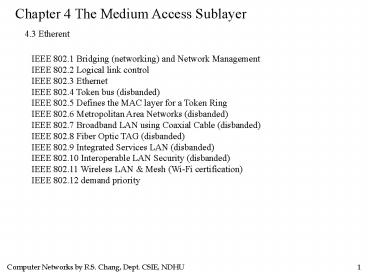
4.3 Etherent
IEEE 802.1 Bridging (networking) and Network
Management IEEE 802.2 Logical link control IEEE
802.3 Ethernet IEEE 802.4 Token bus (disbanded)
IEEE 802.5 Defines the MAC layer for a Token
Ring IEEE 802.6 Metropolitan Area Networks
(disbanded) IEEE 802.7 Broadband LAN using
Coaxial Cable (disbanded) IEEE 802.8 Fiber Optic
TAG (disbanded) IEEE 802.9 Integrated Services
LAN (disbanded) IEEE 802.10 Interoperable LAN
Security (disbanded) IEEE 802.11 Wireless LAN
Mesh (Wi-Fi certification) IEEE 802.12 demand
priority
2
Chapter 4 The Medium Access Sublayer
4.3 Etherent
IEEE 802.13 Cat.6 - 10Gb lan (new founded) IEEE
802.14 Cable modems (disbanded) IEEE 802.15
Wireless PAN IEEE 802.15.1 (Bluetooth
certification) IEEE 802.15.4 (ZigBee
certification) IEEE 802.16 Broadband Wireless
Access (WiMAX certification) IEEE 802.16e
(Mobile) Broadband Wireless Access IEEE 802.17
Resilient packet ring IEEE 802.18 Radio
Regulatory TAG IEEE 802.19 Coexistence TAG IEEE
802.20 Mobile Broadband Wireless Access IEEE
802.21 Media Independent Handoff IEEE 802.22
Wireless Regional Area Network
3
Chapter 4 The Medium Access Sublayer
4.3 Etherent
IEEE 802.3 1-persistent CSMA/CD
4
Chapter 4 The Medium Access Sublayer
4.3 Etherent
5
Chapter 4 The Medium Access Sublayer
4.3 Etherent
To allow larger networks, multiple cables can be
connected by repeaters.
A repeater is a physical layer device. It
receives, amplifies, and retransmits signals in
both directions. As far as the software is
concerned, a series of cable segments connected
by repeaters is no different than a single cable.
6
Chapter 4 The Medium Access Sublayer
4.3 Etherent
Cable topologies. (a) Linear, (b) Spine, (c)
Tree, (d) Segmented
7
Chapter 4 The Medium Access Sublayer
10BASE5 10BASE2 1BASE5
10BROAD36 10BASE-T Ethernet
Cheaper net StarLAN Broadband
Twisted-pair
coaxial cable 50ohm-10mm
coaxial cable 50ohms-5mm
twisted-pair unshielded
coaxial cable 75ohms
2 simplex TP unshielded
medium
10Mbps Manch
10Mbps Manch
1Mbps Manch
10Mbps DPSK
10Mbps Manch
signals
maximum segment
500m
185m
500m
1800m
100m
maximum distance
2.5km
0.925km
2.5km
3.6km
1km
nodes per segment
2
100
30
activity on receiver and transmitter
collision detection
2 active hub inputs
transmission reception
excess current
Notes
slot time512 bits gap time96 bits jam32 to
48 bits
8
Chapter 4 The Medium Access Sublayer
4.3 Etherent
Manchester Encoding
9
Chapter 4 The Medium Access Sublayer
4.3 Etherent
802.3 frame format
single address
0
multicast (all 1's for broadcast)
group address
1
local address
0
No significance outside
one of 246 unique address
global address
1
10
Chapter 4 The Medium Access Sublayer
4.3 Etherent
802.3 frame format
Minimum frame length 64 bytes
11
Chapter 4 The Medium Access Sublayer
4.3 Etherent
802.3 frame format
As the network speed goes up, the minimum frame
length must go up or the maximum cable length
must come down proportionally. For a 2500-meter
LAN operating at 1 Gbps, the minimum frame size
would have to be 6400 bytes. Alternatively, the
minimum frame size could be 64 bytes and the
maximum distance between any two stations 250
meters.
12
Chapter 4 The Medium Access Sublayer
4.3 Etherent
Ethernet Frame Structure v2 (or DIX Ethernet, for
DEC, Intel, Xerox)
7 1 6 6 2
4
preamble SFD DA SA type
CRC
Data
60 to 1514 bytes
synchronize the receiver
Cyclic Redundancy Check
Typegt0x06001536
0800 IPv4 datagram 0806 ARP request/reply 8035
RARP request/reply 86DD IPv6
start frame delimiter
13
Chapter 4 The Medium Access Sublayer
4.3 Etherent
The Binary Exponential Backoff Algorithm
If a frame has collided n successive times, where
nlt16, then the node chooses a random number K
with equal probability from the set
0,1,2,3,...,2m-1 where mmin10,n. The node
then waits for bit times. (slot
time512 bit time)
after first collision
after second collision
after third collision
select one to start transmission
14
Chapter 4 The Medium Access Sublayer
4.3 Etherent
Acknowledgements
As far as CSMA/CD is concerned, an
acknowledgement would be just another frame and
would have to fight for channel time just like a
data frame.
(What is the problem?)
A simple modification would allow speedy
confirmation of frame receipt. All that would be
needed is to reserve the first contention slot
following successful transmission for the
destination station.
15
Chapter 4 The Medium Access Sublayer
4.3 Etherent
Performance
Assume k stations are always ready to transmit
and a constant retransmission probability in each
slot. (A rigorous analysis of the binary
exponential backoff algorithm is complicated.)
If each station transmits during a contention
slot with probability p, the probability A that
some station acquires the channel in that slot is
16
Chapter 4 The Medium Access Sublayer
4.3 Etherent
Performance
The probability that the contention interval has
exactly j slots in it is A(1-A)j-1, so the mean
number of slots per contention is given by
Since each slot has a duration 2t, the mean
contention interval, w, is 2t/A. Assuming optimal
p, the mean number of contention slots is never
more than e, so w is at most 2te?5.4t.
17
Chapter 4 The Medium Access Sublayer
4.3 Etherent
Performance
If the mean frame takes P sec to transmit, when
many stations have frames to send,
channel efficiency
Here we see where the maximum cable distance
between any two stations enters into the
performance figures. The longer the cable, the
longer the contention interval. By allowing no
more than 2.5km of cable and four repeaters
between any two transceivers, the round-trip time
can be bounded to 51.2 msec, which at 10Mbps
corresponds to 512 bits or 64 bytes, the minimum
frame size.
18
Chapter 4 The Medium Access Sublayer
4.3 Etherent
Performance
Let PF/B (frame_length/bandwidth) and tL/C
(cable_length/signal_propagation_speed). For the
optimal case of e contention slots per frame,
channel
efficiency
Increasing network bandwidth or distance (the BL
product) reduces efficiency for a given frame
size. Unfortunately, much research on network
hardware is aimed precisely at increasing this
product. People want high bandwidth over long
distances, which suggests that 802.3 may not be
the best system for these applications.
19
Chapter 4 The Medium Access Sublayer
4.3 Etherent
20
Chapter 4 The Medium Access Sublayer
4.3 Etherent
Many theoretical analysis assume the input
traffic is Poisson. It now appears that network
traffic is rarely Poisson, but self-similar. What
this means is that averaging over long periods of
time does not smooth out the traffic. The
average number of packets in each minute of an
hour has as much variance as the average number
of packets in each second of s minute. The
consequence of this discovery is that most models
of network traffic do not apply to the real world
and should be taken with a grain of salt.
21
Chapter 4 The Medium Access Sublayer
4.3 Etherent
Switched 802.3 LANs
22
Chapter 4 The Medium Access Sublayer
4.3 Etherent
Fast Ethernet
The three primary reasons that the 803 committee
decided to go with a souped-up 802.3 LAN (instead
of a totally new one) were 1. The need to be
backward compatible with thousands of existing
LANs. 2. The fear that a new protocol might have
unforeseen problems. 3. The desire to get the job
done before the technology changed.
23
Chapter 4 The Medium Access Sublayer
4.3 Etherent
Fast Ethernet
The basic idea behind fast Ethernet was simple
keep all the old packet formats, interfaces, and
procedural rules, but just reduce the bit time
form 100 nsec to 10 nsec. Technically, it would
have been possible to copy 10Base5 or 10Base2 and
still detect collisions on time by just reducing
the maximum cable length by a factor of
ten. However, the advantages of 10BaseT wiring
were so overwhelming that fast Ethernet is based
entirely on this design. Thus all fast Ethernet
systems use hubs.
24
Chapter 4 The Medium Access Sublayer
4.3 Etherent
Fast Ethernet
The category 3 UTP scheme, called 100Base-T4,
uses a signaling speed of 25 MHz, only 25 percent
faster than standard 802.3s 20 MHz. To achieve
the necessary bandwidth, 100BaseT4 requires four
twisted pairs.
25
Chapter 4 The Medium Access Sublayer
4.3 Etherent
Fast Ethernet
Of the four twisted pairs, one is always to the
hub, one is always from the hub, and the other
two are switchable to the current transmission
direction. To get the necessary bandwidth,
Manchester encoding is not used, but with modern
clocks and such short distances, it is no longer
needed.
26
Chapter 4 The Medium Access Sublayer
4.3 Etherent
Fast Ethernet
Ternary signals are sent, so that during a single
clock period the wire can contain a 0, a 1, or a
2. With three twisted pairs going in the forward
direction and ternary signaling, any one of the
27 possible symbols can be transmitted, making it
possible to send 4 bits with some redundancy.
Transmitting 4 bits in each of the 25 million
clock cycles per second gives the necessary 100
Mbps.
In addition, there is always a 33.3 Mbps (100/3)
reverse channel using the remaining twisted pair.
This scheme, known as 8B6T, (8 bits map to 6
trits) is not likely to win any prizes for
elegance, but it works with the existing wiring
plant.
27
Chapter 4 The Medium Access Sublayer
4.3 Etherent
Fast Ethernet
For category 5 wiring, the design, 100Base-TX, is
simpler because the wires can handle clock rates
up to 125 MHz and beyond. Only two twisted pairs
per station are used, one to the hub and one from
it. Rather than just use straight binary coding,
a scheme called 4B5B is used at 125 MHz. Every
group of 5 clock periods is used to send 4 bits
in order to give some redundancy, provide enough
transitions to allow easy clock synchronization,
create unique patterns for frame delimiting, and
be compatible with FDDI in the physical layer.
28
Chapter 4 The Medium Access Sublayer
4.3 Etherent
Fast Ethernet
Consequently, 100Base-TX is a full-duplex system
stations can transmit at 100 Mbps and receive at
100 Mbps at the same time. Often 100Base-TX and
100Base-T4 are collectively referred as 100Base-T.
The last option, 100Base-FX, uses two strands of
multimode fiber, one for each direction, so it,
too, is full duplex with 100 Mbps in each
direction. In addition, the distance between a
station and the hub can be up to 2 km.
29
Chapter 4 The Medium Access Sublayer
4.3 Etherent
Fast Ethernet
Two kinds of hubs are possible with 100Base-T4
and 100Base-TX hub all incoming lines are
logically connected, forming a single collision
domain. switches each incoming frame is buffered
on a plug-in line card. Buffered frames are
passed over a high-speed backplane from the
source card to the destination card.
30
Chapter 4 The Medium Access Sublayer
4.3 Etherent
Gigabit Ethernet
The ink was barely dry on the fast Ethernet
standard when the 802 committee bagan working on
a yet faster Ethernet. It was quickly dubbed
gigabit Ethernet and was ratified by IEEE in 1998
under the name 802.3z.
An important design goal remain backward
compatibility
31
Chapter 4 The Medium Access Sublayer
4.3 Etherent
Gigabit Ethernet
All configurations of gigabit Ethernet are
point-to-point.
Each individual Ethernet cable has exactly two
devices on it, no more and no fewer.
32
Chapter 4 The Medium Access Sublayer
4.3 Etherent
Gigabit Ethernet
Two different modes of operation full duplex and
half duplex
The normal mode is full-duplex used when
computers are connected to a switch.
The sender does not have to sense the channel to
see if anybody else is using it because
contention is impossible. So CSMA/CD protocol is
not used.
So the maximum length of the cable is determined
by signal strength issues rather than by the
collision detection issue.
33
Chapter 4 The Medium Access Sublayer
4.3 Etherent
Gigabit Ethernet
Half-duplex is used when the computers are
connected to a hub. A hub does not buffer
incoming frames. So collisions are possible and
CSMA/CD is required.
But now the transmission time for a 64-byte frame
is 100 times faster. So the distance is 100 times
less than Ethernet. That is, only 25 meters.
The 802.3z committee considered a radius of 25
meters to be unacceptable and added two features
to the standard to increase the radius.
34
Chapter 4 The Medium Access Sublayer
4.3 Etherent
Gigabit Ethernet
The first feature, called carrier extension,
essentially tells the hardware to add its own
padding to extend the frame to 512 bytes. Of
course, using 512 bytes to transmit 64 bytes of
data has a line efficiency of 9.
The second feature, called frame bursting, allows
a sender to transmit a concatenated sequence of
multiple frames in a single transmission. If the
total length is less than 512 bytes, the hardware
pads it again.
Just for backward compatibility. Most will use
switches.
35
Chapter 4 The Medium Access Sublayer
4.3 Etherent
Gigabit Ethernet
Cabling
Gigabit Ethernet uses new encoding rules on the
fiber. Manchester encoding at 1Gbps would require
2G baud signal, too difficult and too wasteful.
36
Chapter 4 The Medium Access Sublayer
4.3 Etherent
Gigabit Ethernet
- 8B/10B is used. Each 8-bit byte is encoded as 10
bits. - 256 out of 1024. Two rules are used
- No codeword may have more than four identical
bits in a row. - No codeword may have more than six 0s or six 1s.
In addition, many input bytes have two possible
codewords assigned to them. When there is a
choice, the encoder always chooses the one that
tries to equalize the number of 0s and 1s
transmitted so far.
37
Chapter 4 The Medium Access Sublayer
4.3 Etherent
Gigabit Ethernet
1000Base-T uses a different encoding scheme since
clocking data onto copper wire in 1 nsec is too
difficult. The solution uses four category 5
twisted pairs to allow four symbols to be
transmitted in parallel. Each symbol is encoded
using one of five voltage levels. This scheme
allows a single symbol to encode 00, 01, 10, 11,
or a special value for control purposes. The
clock runs at 125MHz, allowing 1-Gbps operation.
38
Chapter 4 The Medium Access Sublayer
4.3 Etherent
Gigabit Ethernet
Gigabit Ethernet supports flow control which
consists of one end sending a special control
frame to the other end telling it to pause for
some period of time. For gigabit Ethernet, the
time unit for pause is 512 nsec. The maximum is
33.6 msec. 802.3ae 10G Ethernet
39
Chapter 4 The Medium Access Sublayer
4.3 Etherent
IEEE Standard 802.2 Logical Link Control
40
Chapter 4 The Medium Access Sublayer
4.3 Etherent
Why Ethernet is so successful? Last more than 20
years! Ethernet is simple and flexible. Simple
translates into reliable, cheap, and easy to
maintain. Ethernet interworks easily with
TCP/IP. Both IP and Ethernet are
connectionless. Speed can catch up with other
standards.
41
Chapter 4 The Medium Access Sublayer
4.4 Wireless LANS
54Mbps
11Mbps
54Mbps
5GHz ISM band
2.4 GHz
FHSS Frequency Hopping Spread Spectrum DSSS
Direct Sequence Spread Spectrum OFDM Orthogonal
Frequency Division Multiplexing HR-DSSS High
Rate DSSS
42
Chapter 4 The Medium Access Sublayer
4.4 Wireless LANS
802.11 MAC sublayer
(a) The hidden station problem (b) The exposed
station problem
43
Chapter 4 The Medium Access Sublayer
4.4 Wireless LANS
802.11 MAC sublayer
Two modes of operation DCF distributed
coordination function, no central control PCF
point coordination function, the base station
controls all activity in its cell All
implementations must support DCF but PCF is
optional.
44
Chapter 4 The Medium Access Sublayer
4.4 Wireless LANS
802.11 MAC sublayer
- When DCF is employed, 802.11 uses a protocol
called CSMA/CA (CSMA with Collision Avoidance).
Two methods of operation are supported by
CSMA/CA. - In the first method
- When a station wants to transmit, it senses the
channel. If it is idle, it just starts
transmitting. - If the channel is busy, the sender defers until
it is idle and then starts transmitting. - It does not sense the channel while transmitting.
- If a collision occurs, the colliding stations
wait a random time, using Ethernet binary
exponential backoff algorithm, and try again
later.
45
Chapter 4 The Medium Access Sublayer
4.4 Wireless LANS
802.11 MAC sublayer
The other method of CSMA/CA operation is based on
MACAW and uses virtual channel sensing.
A wants to send to B. C is within range of A. D
is within range of B, but not A. (NAV network
allocation vector)
46
Chapter 4 The Medium Access Sublayer
4.4 Wireless LANS
802.11 MAC sublayer
Wireless networks are noisy and unreliable. If a
frame is too long, it has very little chance of
getting through undamaged. So 802.11 allows
frames to be fragmented into smaller pieces, each
with its own checksum.
Stop and Wait is used.
47
Chapter 4 The Medium Access Sublayer
4.4 Wireless LANS
802.11 MAC sublayer
In PCF, the base stations polls the other
stations, asking them if they have any frames to
send. The basic mechanism is for the base
station to broadcast a beacon frame periodically
(10 to 100 times per second). Battery life is
always an issue with mobile devices, so in
802.11, the base station can direct a mobile
station to go into sleep until explicitly
awakened by the base station or the user.
48
Chapter 4 The Medium Access Sublayer
4.4 Wireless LANS
802.11 MAC sublayer
PCF and DCF can coexist within one cell.
SIFS Short InterFrame Spacing, PIFS PCF IFS,
DIFS DCF IFS, EIFS Extended IFS
49
Chapter 4 The Medium Access Sublayer
4.4 Wireless LANS
source and dest base station addr. for intercell
traffic
802.11 Frame Structure
process frames in order
data control management
intercell
RTS CTS
power control
more fragment
wired equivqlent privacy
More data
50
Chapter 4 The Medium Access Sublayer
4.4 Wireless LANS
802.11 Services
- Five distribution services and four station
services - Five distribution services
- Association connect to a base station
- Disassociation break the association either by
the base station or the station - Reassociation change preferred base station
- Distribution how to route frames sent to the
base station - Integration translate from 802.11 to non-802.11
(in address scheme or frame format)
51
Chapter 4 The Medium Access Sublayer
4.4 Wireless LANS
802.11 Services
- Four intercell station services
- Authentication a station proves its knowledge of
the secret key by encrypting the challenge frame
and sending it back to the base station - Deauthentication
- Privacy manage the encryption and decryption
using RC4 - Data delivery
52
Chapter 4 The Medium Access Sublayer
4.5 Broadband Wireless
802.16 Broadband Wireless Access Running fiber,
coaxial, or even category 5 twisted pair to
millions of homes and businesses is prohibitively
expensive! What is a competitor can do? The
wireless local loop The wireless last mile The
wireless MAN (metropolitan area network)
53
Chapter 4 The Medium Access Sublayer
4.5 Broadband Wireless
Comparison of 802.11 with 802.16
- 802.16 provides service to buildings, and
buildings are not mobile. - Buildings can have more than one computer in
them. - Better radios are available for buildings. So
802.16 can use full-duplex communications. - In 802.16, the distances involved can be several
kilometers, affect signal-to-noise ratio and need
security and privacy. - More bandwidth is needed. Hence 802.16 has to
operate in higher 10-66 GHz band, thus require a
completely different physical layer. - Error handling is much more important in 802.16.
- 802.16 should support QoS.
54
Chapter 4 The Medium Access Sublayer
4.5 Broadband Wireless
The 802.16 protocol stack
55
Chapter 4 The Medium Access Sublayer
4.5 Broadband Wireless
The 802.16 physical layer
56
Chapter 4 The Medium Access Sublayer
4.5 Broadband Wireless
The 802.16 physical layer
Frames and time slots for time division duplexing.
57
Chapter 4 The Medium Access Sublayer
4.5 Broadband Wireless
The 802.16 MAC layer
- All connection-oriented services
- 4 Service Classes
- Constant bit rate service
- Real-time variable bit rate service
- Non-real-time variable bit rate service
- Best efforts service
58
Chapter 4 The Medium Access Sublayer
4.5 Broadband Wireless
Encryption key
The 802.16 frame structure
(a) A generic frame. (b) A bandwidth request
frame.
Encrypted or not
Final checksum present or not
59
Chapter 4 The Medium Access Sublayer
4.5 Broadband Wireless
WiMAX, the Worldwide Interoperability for
Microwave Access, is a telecommunications
technology aimed at providing wireless data over
long distances in a variety of ways, from
point-to-point links to full mobile cellular type
access. It is based on the IEEE 802.16
standard, which is also called Wireless MAN. The
name WiMAX was created by the WiMAX Forum, which
was formed in June 2001 to promote conformance
and interoperability of the standard. The forum
describes WiMAX as "a standards-based technology
enabling the delivery of last mile wireless
broadband access as an alternative to cable and
DSL."
60
Chapter 4 The Medium Access Sublayer
4.6 Bluetooth
Bluetooth is an industrial specification for
wireless personal area networks (PANs). Bluetooth
provides a way to connect and exchange
information between devices such as mobile
phones, laptops, PCs, printers, digital cameras,
and video game consoles over a secure, globally
unlicensed short-range radio frequency. The
Bluetooth specifications are developed and
licensed by the Bluetooth Special Interest Group.
61
Chapter 4 The Medium Access Sublayer
4.6 Bluetooth
Architecture
Two piconets can be connected to form a
scatternet.
62
Chapter 4 The Medium Access Sublayer
4.6 Bluetooth
Profiles
63
Chapter 4 The Medium Access Sublayer
4.6 Bluetooth
Protocol stack
The 802.15 version of the Bluetooth protocol
architecture.
64
Chapter 4 The Medium Access Sublayer
4.6 Bluetooth
Frame structure
Flow control (slave buffer full)
Stop-and-wait sequence number
Piggyback ack
65
Chapter 4 The Medium Access Sublayer
4.7 Datalink Layer Switching
Bridge
A
C
LANs can be connected by devices called bridges,
which operate in the data link layer. Bridges do
not examine the network layer header.
66
Chapter 4 The Medium Access Sublayer
4.7 Datalink Layer Switching
Router
A
C
Router
In contrast, a router examines network layer
headers.
67
Chapter 4 The Medium Access Sublayer
4.7 Datalink Layer Switching
Multiple LANs connected by a backbone to handle a
total load higher than the capacity of a single
LAN.
68
Chapter 4 The Medium Access Sublayer
4.7 Datalink Layer Switching
Why a single organization may end up with
multiple LANs? (to need bridges)
1. Autonomy of departments to choose their own
types of LANs 2. Cheaper to have separate LANs
than to run a single large LANs 3. Load
splitting 4. Physical distance is too great.
(For example, gt2.5km in 802.3) 5. More
reliable 6. More secure
69
Chapter 4 The Medium Access Sublayer
4.7 Datalink Layer Switching
Operation of a LAN bridge from 802.11 to 802.3.
70
Chapter 4 The Medium Access Sublayer
4.7 Datalink Layer Switching
Bridges from 802.x to 802.y
You might naively think that a bridge from 802
LAN to another one would be completely trivial.
Such is not the case. Each of the nine
combinations of 802.x to 802.y has its own unique
set of problems.
General problems 1. Different frame format 2.
Different data rate 3. Different maximum frame
length
71
Chapter 4 The Medium Access Sublayer
4.7 Datalink Layer Switching
Bridges from 802.x to 802.y
The IEEE 802 frame formats. The drawing is not
to scale.
72
Chapter 4 The Medium Access Sublayer
4.7 Datalink Layer Switching
Transparent Bridges
Plug and play bridge
When a frame arrives, a bridge must decide
whether to discard or forward it, and if the
latter, on which LAN to put the frame. The
decision is made by looking up the destination
address in a big (hash) table inside the bridge.
73
Chapter 4 The Medium Access Sublayer
4.7 Datalink Layer Switching
Transparent Bridges
When the bridges are first plugged in, all the
hash tables are empty. None of the bridges know
where any of the destinations are, so they use
the flooding algorithm.
Use backward learning algorithm. If a frame comes
from LAN1 with source address A, the bridge
learns that host A is in LAN1.
The topology can change as machines and bridges
are powered up and down and moved around. To
handle dynamic topologies, whenever a hash table
entry is updated, the time is recorded.
Periodically, a process in the bridge scans the
hash table and purges all entries more than a few
minutes old.
74
Chapter 4 The Medium Access Sublayer
4.7 Datalink Layer Switching
Transparent Bridges
Routing procedure for a transparent bridge 1. If
the destination and source LANs are the same,
discard the frame. 2. If the destination and
source LANs are different, forward the frame. 3.
If the destination LAN is unknown, use flooding.
75
Chapter 4 The Medium Access Sublayer
4.7 Datalink Layer Switching
Transparent Bridges
Avoid looping in parallel bridges.
76
Chapter 4 The Medium Access Sublayer
4.7 Datalink Layer Switching
Transparent Bridges
Spanning Tree Bridges
77
Chapter 4 The Medium Access Sublayer
4.7 Datalink Layer Switching
Transparent Bridges
Spanning Tree Bridges
78
Chapter 4 The Medium Access Sublayer
4.7 Datalink Layer Switching
Transparent Bridges
Spanning Tree Bridges
To build the spanning tree, first the bridges
have to choose one bridge to be the root of the
tree. They make this choice by having each one
broadcast its serial number, installed by the
manufacturer, and guaranteed to be unique
worldwide. The bridge with the lowest serial
number becomes the root. Next, a tree of shortest
paths from the root to every bridge and LAN is
constructed.
79
Chapter 4 The Medium Access Sublayer
4.7 Datalink Layer Switching
Source Routing Bridges
Source routing assumes that the sender of each
frame knows whether or not the destination is on
its own LAN. When sending a frame to a different
LAN, the source machine sets the high-order bit
of the source address to 1, to mark it.
Furthermore, it includes in the frame header the
exact path that the frame will follow.
80
Chapter 4 The Medium Access Sublayer
4.7 Datalink Layer Switching
Source Routing Bridges
This path is constructed as follows. Each LAN has
a unique 12-bit number, and each bridge has a
4-bit number that uniquely identifies it in the
context of its LANs. A route is then a sequence
of bridge, LAN, bridge, LAN, numbers.
For example, the route from A to D (L1, B1, L2,
B2, L3)
81
Chapter 4 The Medium Access Sublayer
4.7 Datalink Layer Switching
Source Routing Bridges
A source routing bridge is only interested in
those frames with the high-order bit of the
destination set to 1. For each such frame, it
scans the route looking for the number of the LAN
on which the frame arrived. If this LAN number
is followed by its own bridge number, the bridge
forwards the frame onto the LAN whose number
follows its bridge number in the route.
82
Chapter 4 The Medium Access Sublayer
4.7 Datalink Layer Switching
Source Routing Bridges
Three possible implementations 1. Software the
bridge runs in promiscuous mode, copying all
frames to its memory to see if they have the
high-order destination bit set to 1. If so, the
frame is inspected further. 2. Hybrid the
bridges LAN interface inspects the high-order
destination bit and only accepts frame with the
bit set. This interface is easy to build into
hardware and greatly reduces the number of frames
the bridge must inspect.
83
Chapter 4 The Medium Access Sublayer
4.7 Datalink Layer Switching
Source Routing Bridges
Three possible implementations 3. Hardware the
bridges LAN interface not only checks the
high-order destination bit, but it also scans the
route to see if this bridge must do forwarding.
Only frames that must actually be forwarded are
given to the bridge. This implementation requires
the most complex hardware but wastes no bridge
CPU cycles because all irrelevant frames are
screened out.
84
Chapter 4 The Medium Access Sublayer
4.7 Datalink Layer Switching
Source Routing Bridges
Implicit in the design of source routing bridge
is that every machine in the internetwork knows,
or can find, the best path to every other
machine. How these routes are discovered is an
important part of the source routing bridge.
The basic idea is that if a destination is
unknown, the source issues a broadcast frame
asking where it is. This discovery frame is
forwarded by every bridge so that it reaches
every LAN on the internetwork. When the reply
comes back, the bridges record their identity in
it, so that the original sender can see the exact
route taken and ultimately choose the best route.
85
Chapter 4 The Medium Access Sublayer
4.7 Datalink Layer Switching
Source Routing Bridges
While this algorithm clearly finds the best route
(it finds all routes), it suffers from a frame
explosion.
3N-1 frames here.
86
Chapter 4 The Medium Access Sublayer
4.7 Datalink Layer Switching
Comparison of 802 Bridges
87
Chapter 4 The Medium Access Sublayer
4.7 Datalink Layer Switching
Remote Bridges
Point to point protocol used between bridges 1.
Choose some standard point-to-point protocol,
putting complete MAC frames in the payload field
(best if all LANs are identical) 2. Strip off the
MAC header at source bridge, put back at
destination (can not catch errors caused by bad
bridge memory)
88
Chapter 4 The Medium Access Sublayer
4.7 Datalink Layer Switching
Repeaters, Hubs, Bridges, Switches, Routers, and
Gateways
89
Chapter 4 The Medium Access Sublayer
4.7 Datalink Layer Switching
Repeaters, Hubs, Bridges, Switches, Routers, and
Gateways
(a) A hub. (b) A bridge. (c) a switch.
90
Chapter 4 The Medium Access Sublayer
4.7 Datalink Layer Switching
Virtual LANs
A building with centralized wiring using hubs and
a switch.
91
Chapter 4 The Medium Access Sublayer
4.7 Datalink Layer Switching
Virtual LANs
(a) Four physical LANs organized into two VLANs,
gray and white, by two bridges. (b) The same 15
machines organized into two VLANs by switches.
92
Chapter 4 The Medium Access Sublayer
4.7 Datalink Layer Switching
Virtual LANs 802.1Q Standard
Transition from legacy Ethernet to VLAN-aware
Ethernet. The shaded symbols are VLAN aware.
The empty ones are not.
93
Chapter 4 The Medium Access Sublayer
4.7 Datalink Layer Switching
Virtual LANs 802.1Q Standard
The 802.3 (legacy) and 802.1Q Ethernet frame
formats.
94
Chapter 4 The Medium Access Sublayer
Summary
95
Exercises Page 338 Problems 2,3 Page 339
Problems 12, 15 Page 340 Problems 21, 23 Page
341 Problems 37, 40
Recommended
CrystalGraphics Presentations


