
Wireless Communications - PowerPoint PPT Presentation
1 / 73
Title: Wireless Communications
1
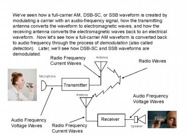
Weve seen how a full-carrier AM, DSB-SC, or SSB
waveform is created by modulating a carrier with
an audio-frequency signal, how the transmitting
antenna converts the waveform to electromagnetic
waves, and how the receiving antenna converts the
electromagnetic waves back to an electrical
waveform. Now lets see how a full-carrier AM
waveform is converted back to audio frequency
through the process of demodulation (also called
detection). Later, well see how DSB-SC and SSB
waveforms are demodulated.
Radio Frequency Current Waves
Antenna
Radio Waves
Microphone
Transmitter
Audio Frequency Voltage Waves
Antenna
Receiver
Audio Frequency Voltage Waves
Radio Frequency Current Waves
Speaker
2
A full-carrier AM waveform is shown below. The
modulated carrier is shown in blue, while the
envelope is shown in red. Its important to
realize that the modulated carrier (in blue) is
transmitted, but the envelope is not. The
envelope is simply the imaginary waveform which
would result from connecting the peaks of the
modulated carrier waveform.
3
The modulated carrier waveform which is actually
transmitted looks like this
4
The task of the receiver, in simplest terms is to
connect the peaks of the modulated carrier,
creating an actual envelope waveform from the
modulated carrier,
5
And then to remove the carrier, leaving the
audio-frequency envelope. These two tasks
together comprise the process called demodulation
or detection.
6
Demodulation of a full-carrier AM signal is
accomplished by processing the modulated carrier
in such a way that the envelope waveform, a copy
of the sound waveform which was used to modulate
the carrier, is recreated. At the same time,
the RF carrier is removed and discarded.
7
As you may recall from a previous section, the
depiction of the envelope shown here is the
time-domain view of the waveform. The variable
which appears on the horizontal axis is called
the domain, and the variable which appears on the
vertical axis is called the range.
8
The time-domain view of an actual signal can be
displayed on an instrument called an
oscilloscope. The time-domain view shows the
instantaneous signal voltage for all values of
time from (in this case) t 0 (an arbitrarily
chosen starting time) to t 0.020 seconds.
9
Here again is the time domain view of the RF
signal, an amplitude-modulated carrier, that we
want to demodulate.
10
Here is the frequency domain view of the RF
signal (that is, the modulated carrier). Since
this is the frequency-domain view, the variable
which appears on the horizontal axis is frequency
rather than time The frequency domain view shows
how the signals energy is distributed or spread
across a range of frequencies.
Energy
-fcarrier
0 Hz.
fcarrier
11
As you can see, part of the energy (half of it,
to be exact) is concentrated at the carrier
frequency. The rest is spread over two frequency
bands, the upper sideband and the lower sideband.
Energy
-fcarrier
0 Hz.
fcarrier
12
The audio waveform which demodulation should
accurately reproduce looks like this in the
frequency domain.
Energy
-fcarrier
0 Hz.
fcarrier
13
The audio waveform can be reproduced by shifting
the RF signal (that is, the modulated carrier)
downward in frequency
Energy
-fcarrier
0 Hz.
fcarrier
14
to baseband (the band which was occupied by the
original audio signal). At the same time, the
carrier is removed and discarded
Energy
-fcarrier
0 Hz.
fcarrier
15
resulting in the signal were trying to
reproduce, which means were done. At least, this
looks like the original audio in the frequency
domain. What about the time domain? Theres a
principal of signal analysis (youll see a proof
in a couple of years, dont worry about it now)
which says that if the frequency-domain views of
two waveforms are identical, then the time-domain
views are also identical.
Energy
-fcarrier
0 Hz.
fcarrier
16
This means that if weve successfully processed
the RF signal (the amplitude-modulated carrier)
in such a way as to extract the modulating signal
(that is, to reproduce the audio waveform which
was used at the transmitter to amplitude-modulate
the carrier) in the frequency domain, then weve
successfully reproduced the original audio
waveform in the time domain as well. We are, in
fact, done.
Energy
-fcarrier
0 Hz.
fcarrier
17
Actually, we would be done if we were
mathematicians. Im an engineer, and you will be
one, so were not quite done yet. We have to
design an electronic circuit which will
demodulate the RF signal. From the frequency
domain viewpoint, the RF signal consists of a
carrier and upper and lower sidebands. The
first part of the demodulation process,
connecting the dots between peaks of the
modulated carrier waveform to draw the
envelope, has the effect of translating the RF
signal to baseband, or copying the sidebands and
placing the copies back where they were before
they were used to modulate the carrier.
18
Connecting the peaks of the modulated carrier
sounds simple, and it is, but the method of
accomplishing it probably doesnt seem
obvious. Its not obvious, but it has been around
for about a century. If you ever built a
crystal radio as a child, youve built a simple
envelope detector.
19
An envelope detector starts with an electronic
device called a diode. That word literally means
a device with two electrical terminals. There
are many types of two-terminal devices besides
those normally called diodes. The word diode
normally refers to a type of two-terminal device
which allows current to flow in one direction but
not the other, forward but not backward. The
schematic symbol for a diode is shown below, with
the direction current is allowed to flow through
it.
Current can flow forward
Current cannot flow backward
20
Electrical current can be thought of as water
flowing through a pipe, with a wire or other
electrical conductor playing the role of the
pipe. Electrical current is measured in units
called amperes (or amps for short), which
indicate the amount of electrical charge moving
through a section of wire in one second. Again
comparing electrical current to water flowing
through a pipe, the flow rate of water being
pumped from one place to another is measured in
gallons per second. A current of 1 amp is an
electrical flow rate of 1 coulomb (the unit of
electrical charge) per second.
Current can flow forward
Current cannot flow backward
21
Water does not flow through a pipe unless it is
pushed (pumped) by applying pressure at one end
of the pipe, or pulled (sucked) by applying
negative pressure at the other. Water does not
flow unless pressure is applied because any
real-world pipe resists the flow of water through
it, because of friction between the flowing water
and the walls of the pipe. If you touched a pipe
through which water was flowing very fast, it
would probably feel warm because of that
friction. In a similar way, any real world
electrical conductor (with the exception of
superconductors, which are not practical for most
uses) resists the flow of electricity. Current
will not flow through a wire unless it is
pushed by the application of a sort of
electrical pressure. This electrical pressure is
actually called electromotive force, and is
measured in units of volts. Electromotive force
is usually referred to as voltage, or sometimes
as electrical potential or just potential.
22
Devices like diodes also resist the flow of
current. A diode exhibits very little
resistance to current flowing in the forward
direction, but very great resistance to current
flowing in the reverse direction. Electrical
resistance is measured in units called ohms. An
electromotive force of one volt applied to a
resistance of one ohm causes a current of 1
ampere to flow through the resistance.
Increasing the voltage causes the current to
increase, but increasing the resistance causes
the current to decrease.
Current can flow forward
Current cannot flow backward
23
Voltage could be applied to a diode by connecting
it to a sort of electrical pump, like a battery
or power supply. Batteries and power supplies are
sources of voltage, so the general term form them
is voltage source. The diagram below shows a
battery (represented by its schematic symbol)
connected to one terminal of the diode. The
terminal of the diode which is connected to the
diode, the blunt end of the arrow, is called the
anode. The other end is called the cathode. The
battery has a positive terminal (indicated here
by the ) and a negative terminal, which means
it has the property of polarity You might think
that connecting the diode to the battery in this
way would result in current flowing through the
diode, but youd be wrong.
1 volt
24
If the other end of the diode (the cathode) is
connected to the other terminal of the battery,
current can flow around the closed loop, or
closed circuit. A closed circuit is necessary for
current to flow. There is a problem with this
particular circuit, however. Its a short
circuit. The wires which connect the battery to
the diode can be assumed to have very little
resistance. Ideal wires (which dont exist,
except for superconductors)) could be assumed to
have zero resistance
1 volt
25
When current flows forward through the diode, the
diode also has very low resistance. This means
nothing in the path of the current flow has more
than a tiny bit of resistance. Because the
resistance to current flow is so small, the
current becomes very large. Drawing such a large
current from the voltage source (the battery)
would probably damage or destroy it.
1 volt
26
To prevent damage to the voltage source, we can
add another element to the circuit a
resistor. The zigzag symbol in this schematic
diagram represents a resistor. The letter R
represents its resistance, in ohms. The amount of
current which flows around the circuit depends on
the resistors resistance and the voltage applied
to it.
1 volt
R
27
The circuit shown here consists of three circuit
elements (a voltage source, a diode, and a
resistor). Each of these elements has two
terminals. A terminal is a point at which one
element can be connected to another through a
wire. For example, a flashlight batter has two
terminals, one at each end.
Resistors Upper Terminal
1 volt
R
Resistors Lower Terminal
28
Any two-terminal circuit element (and there are
elements with more than two terminals, but none
with less than 2) can have a different voltage
(remember, voltage is like electrical pressure)
at its two terminals. If the upper terminal of
the resistor has a voltage of 1 volt (compared
with the voltage at the batterys negative
terminal) we say the voltage at that terminal is
1 volt. If, at the same time, the voltage at the
lower terminal is 0 volts (the same as the
voltage at the batterys negative terminal which
serves as a reference level or ground), then we
say the voltage at that terminal is zero
volts. The voltage drop (or potential difference)
across the resistor is the difference between the
two terminal voltages
Resistors Upper Terminal
1 volt
R
Resistors Lower Terminal
29
In this example, that voltage drop (potential
difference) is equal to the voltage at the upper
terminal minus the voltage at the lower terminal
The terminal with the greater voltage is
indicated by the sign, and the terminal with
the lesser voltage is indicated by the -. The
voltage across the two terminals (the potential
difference) is represented by E.
Resistors Upper Terminal 1 Volt
1 volt
R
E 1 volt
-
Resistors Lower Terminal 0 Volts
30
Lets see how much current would flow through the
resistor. We dont have to actually measure the
current (using an ammeter) if we know the voltage
acrossit. If we know how much resistance the
resistor has (how many ohms) and the voltage drop
(or potential difference) across it (between the
two terminals), we can calculate how much current
flows through it using Ohms law. Ohms law says
that the current (in amperes) flowing through an
element is equal to the potential difference
between the two terminals (the voltage drop
across the element, in volts) divided by the
elements resistance (in ohms)
I
1 volt
E 1 volt
R
-
31
If E is one volt and R is 1000 ohms (1000 W, or 1
kilohm, or just 1 kW), then the current I is
0.001 amperes, or 1 milliampere (ma.). The prefix
milli means one thousandth of, so 1
milliampere is the same as one thousandth of an
ampere, or 0.001 A.
I
1 volt
E 1 volt
R
-
You may be wondering why the symbol W is used
for ohm. W is the Greek letter omega.
Scientists love to use Greek letters as symbols,
and omega sounds a little like ohm, so its
become common to use W as shorthand ohm.
32
If we did not know the batterys voltage, but
could measure the current flowing through the
resistor, we could calculate the voltage across
the resistor by solving Ohms law for E
If I were 0.005 A (5 ma) and R were 1 kW, then E
would be 0.5 V (500 mV) When current flows in the
forward direction, the resistance of the diode is
very small. The voltage drop across the diode
is therefore also very small, and nearly all of
the battery voltage appears across the resistor.
I
1 volt
E 1 volt
R
-
33
On the other hand, if we tried to make current
flow in the other direction by reversing the
battery voltage, the reverse current flow would
be blocked by the diode. The current would be
zero amperes, but Ohms law would still apply
When the battery voltage is positive, current
flows. The voltage across the resistor is equal
to the battery voltage. When the battery voltage
is negative, no current flows. The voltage
across the resistor is zero.
I
-1 volt
E 1 volt
R
-
34
If we replace the battery (which has a constant
voltage, either positive or negative) with a
voltage source which reverses polarity
I
-1 volt
E 1 volt
R
-
35
the schematic diagram looks like this
I
1 volt
E 1
R
-
36
And the source voltage waveform looks like this.
Notice that instead of being equal to 1 volt at
all times, never changing, the voltage now varies
continually and reverses twice per cycle.
37
The voltage across the resistor now exhibits a
waveform that looks like this. The resistor
voltage is equal to the source voltage when its
positive and current is flowing through the
diode, and the resistor voltage is zero when the
diode blocks the flow of current.
38
Here are the source voltage and the resistor
voltage, shown together. The resistor voltage
isnt what we want yet, because it doesnt
connect the peaks of the source waveform. If it
did connect the peaks, wed have an envelope
detector. We arent there yet, but were getting
closer.
39
To construct a circuit which will extract the
envelope from an amplitude modulated carrier,
thus reproducing the audio waveform which was
used to modulate the carrier, well need another
type of circuit element.
40
That type of element is called a capacitor. The
capacitor is the element designated C in the
diagram below. A capacitor stores electrical
charge. It also stores voltage. It isnt a
battery.
1 volt
VC
C
-
41
The function of a capacitor can be illustrated by
using the plumbing analogy. Suppose we have a
pipe coming from a pump. The pump develops a
pressure designated P, and the pipe is
interrupted by a valve. The valve is currently
closed. The pressure in the pipe to the left of
the valve is equal to P, the pump pressure
The pressure to the right of the valve is zero.
Valve
Pump Pressure P
42
The pump represents a voltage source (voltage is
electrical pressure). The pipe represents a
wire. The valve represents an electrical
switch. Now well add a tank, connected to the
pipe. The tank stores water, and represents a
capacitor. The tank is initially empty, to the
water perssure in the tank is zero.
Tank
Pump Pressure P
Valve
43
If the valve is opened, water starts to flow from
the pump to the tank because the pump pressure is
greater than the initial tank pressure. The tanks
starts to fill. The level of water in the tank
rises, so the pressure in the tank (measured at
the bottom of the tank, where the pipe empties
into it) increases. Well designate the pressure
in the tank as PT.
Tank
Pump Pressure P
Pressure PT
Valve
44
The water level and pressure in the tank continue
to increase, until the tank pressure equals the
pump pressure. When the tank pressure, which is
trying to reverse the flow of water, equals the
pump pressure, the net pressure causing water to
flow becomes zero. The flow of water into the
tank ceases. The water level and pressure in the
tank stop increasing, but dont decrease.
Tank
Pump Pressure P
Pressure PT
Valve
45
If the pump pressure were to increase at this
point, water would again flow into the tank until
the pressure in the tank equals the pump
pressure. If the pump pressure were to decrease,
water would flow backward out of the tank until
the pressures equalize. As long as the valve is
open, the tank pressure equals the pump pressure.
Tank
Pump Pressure P
Pressure PT
Valve
46
If we close the valve, water cannot flow either
into or out of the tank. With the valve closed,
we could turn the pump off (making the pump
pressure zero), but the tank pressure would
remain where it was before the valve was closed.
Tank
Pump Pressure P
Pressure PT
Valve (closed)
47
Suppose the valve is a check valve, which allows
water to flow in only one direction toward the
tank. The check valve, which automatically opens
when the pressure to its left (the pump pressure)
is greater than the pressure to its right (the
tank pressure), represents a diode. A diode may
be thought of as an electrical check valve.
Tank
Pump Pressure P
Pressure PT
Check Valve
48
You probably know what a check valve is if youve
ever lived in a house in which the storm sewers
tended to back up into the basement (through the
floor drain) during a hard rainstorm. In such
houses, a check valve is often installed between
the basement drain and the sewer, to keep sewer
water from flowing backward toward the basement
drain.
Tank
Pump Pressure P
Pressure PT
Check Valve
49
The check valve is normally open, but
automatically closes if the pressure on the sewer
side of the valve is greater than the pressure on
the basement drain side.
Tank
Pump Pressure P
Pressure PT
Check Valve
50
The check valve, which automatically opens when
the pressure to its left (the pump pressure) is
greater than the pressure to its right (the tank
pressure), represents a diode. A diode may be
thought of as an electrical check valve.
Tank
Pump Pressure P
Pressure PT
Check Valve
51
Now the tank can fill when the pump pressure is
greater than the tank pressure, but it cannot
drain. The pressure in the tank can only
increase. The pressure in the tank cannot
decrease.
Tank
Pump Pressure P
Pressure PT
Check Valve
52
Heres the electrical equivalent. The diode
plays the role of the check valve, and the
capacitor plays the role of the tank. As the tank
pressure could only increase and never decrease,
the capacitor voltage can only increase and never
decrease.
-1 volt
VC
C
-
53
The resulting capacitor waveform is shown below.
I appears to connect the peaks, which is what we
wanted.
54
In this circuit the capacitor voltage remains at
the level of the highest peak. It will not
follow a waveform with decreasing peaks. It
needs to be modified.
55
Returning to the pump/check valve/tank analogy,
we add a small-diameter pipe (small compared to
the diameter of the pipe connecting the tank and
the pump) through which the tank constantly
drains. It drains very slowly, compared with
the rate at which it fills when the pump pressure
increases.
Tank
Pump Pressure P
Pressure PT
Check Valve
Drain
56
The capacitor can be allowed to drain slowly by
providing a path for charge to leave it when the
diode is not conducting. This path is provided by
the resistor, which connects the upper terminal
of the capacitor, which happens to be more
positive, to the negative terminal of the voltage
source. The resistor is chosen so that the
current flowing out of the capacitor (Idischarge)
is much lower than the current which can flow
into it through the diode (Icharge).
Icharge
Idischarge
-1 volt
R
VC
C
-
57
The resulting capacitor voltage waveform does
follow an envelope with decreasing peaks, as
shown below.
58
Here is a plot of the capacitor voltage versus
time, along with the input waveform (an
amplitude-modulated carrier), over two cycles of
the envelope. As you can see, the capacitor
voltage waveform is a very good approximation of
the envelope waveform.
59
This is the result in the frequency domain The
audio waveform, which was carried by the carrier
as its envelope, has been recovered by separating
it from the carrier waveform and discarding the
carrier.
Energy
-fcarrier
0 Hz.
fcarrier
60
In the early days of radio, receivers consisting
of little more than this type of envelope
detector were very common. They were called
crystal sets, because the diode was made from a
crystal of a material called galena. Galena is
a type of lead ore. The diode was formed by
making one connection to the galena crystal
through a contact with a large surface area, but
the other connection was made with a very fine
wire called a cats whisker. The radio
operator would move the cats whisker around
until he found a sensitive spot on the crystal.
This trial-and-error process was called tickling
the galena. A simple tuning coil was often
added to the crystal detector, usually consisting
of a coil of magnet wire wound on a cylindrical
cardboard oatmeal box. The radio was crudely
tuned by adjusting a sliding contact along the
length of the tuning coil. During world war II,
allied POWs sometimes fashioned a simple variant
of the crystal radio to listen to German radio
broadcasts. In place of the galena crystal, they
would use a razor blade (the old-fashioned kind
which was simply a thin, flat steel sheet with a
sharpened edge on both sides. A safety pin was
used for the cats whisker.
61
A block diagram of the simplest crystal radio
looks like this
Antenna
Earphones
Envelope Detector
62
The antenna takes the place of the voltage source
in our envelope detector schematic diagram. The
input voltage waveform is electromagnetically
induced between the antenna and ground by the
transmitted electromagnetic field. Earphones are
used because the envelope detector does not
produce enough power to drive a speaker.
Antenna
Earphones
Envelope Detector
63
The voltage waveform induced between the antenna
and ground is not very large, which means the
radio is not very sensitive.
Antenna
Earphones
Envelope Detector
64
Advances in technology soon made it possible to
build electronic amplifiers, which could take a
small voltage waveform and make it larger. An
RF amplifier could be placed between the antenna
and the detector, to strengthen the signal going
into the detector. This would also strengthen AF
signal coming out of the detector.
Antenna
Earphones
Envelope Detector
RF Amplifier
65
Of course, it was also possible to follow the
detector with an audio (AF) amplifier. It soon
became common practice to make the RF amplifier a
narrow band device, which would amplify a signal
on the frequency it was tuned to, but not amplify
nearby frequencies. The radio was tuned by
adjusting the frequency which was amplified.
This type of radio was called tuned RF, or TRF.
Antenna
Earphones
Envelope Detector
AF Amplifier
RF Amplifier
66
Unfortunately, its very difficult to design an
RF amplifier which is highly selective
(narrowband) and tunable at the same time. Its
much more practical to design a selective RF
amplifier which operates at a fixed
frequency This led to the next major advance in
radio receivers
Antenna
Local Oscillator (LO)
AF Output
RF Amplifier (wideband)
IF Amplifier
AF Amplifier
Envelope Detector
Mixer
67
In this type of receiver, the RF signal is
translated or converted downward in frequency
(downconverted) by multiplying (mixing) it with a
fixed-amplitude waveform of a different
frequency. That waveform was generated by the
local oscillator, or LO. The result of this
mixing process was a copy of the RF signal, but
reproduced at a frequency equal to the RF input
frequency minus the LO frequency. This
difference frequency was called the intermediate
frequency, or IF.
Local Oscillator (LO)
Antenna
fRF
fIF
fLO
AF Output
RF Amplifier (wideband)
IF Amplifier
AF Amplifier
Envelope Detector
Mixer
68
The relationship between the RF, IF and LO
frequencies is
Or, if we make fIF fixed, and set fLO as required
to convert the desired frequency fRF to fIF,
In this type of receiver, the radio is tuned by
simply tuning the LO frequency so the desired
transmitter frequency is downconverted to fIF.
Local Oscillator (LO)
Antenna
fRF
fIF
fLO
AF Output
RF Amplifier (wideband)
IF Amplifier
AF Amplifier
Envelope Detector
Mixer
69
This proved to be such a great improvement over
the TRF approach that it is still in widespread
use today. In the old days, the process of
mixing two frequencies to get a third was called
heterodyning, and this receiver architecture is
called superheterodyne.
The superheterodyne (superhet, for short)
receiver was invented in 1919 by Edwin Armstrong.
Local Oscillator (LO)
Antenna
fRF
fIF
fLO
AF Output
RF Amplifier (wideband)
IF Amplifier
AF Amplifier
Envelope Detector
Mixer
70
Heres a frequency-domain depiction of a
full-carrier, double-sideband AM signal. fRF is
equal to the carrier frequency. WOWO in Fort
Wayne transmits on 1190 KHz.
Energy
-fRF
0 Hz.
fRF 1190 KHz
71
To downconvert the WOWO signal to 455 KHz, which
is often used as an intermediate frequency, we
would tune the LO to 1190 455 KHz, or 745
KHz. This results in the RF signal being
downconverted to the IF frequency, 455 KHz.
Energy
-fRF
-fIF
-fIF
0 Hz.
fRF 1190 KHz
72
To receive WLS-AM in Chicago, the Big 89 (890
KHz), we would change the LO frequency to 445
KHz. This would shift WLS at 890 KHz into the
IF amplifiers passband, centered at 455 KHz. At
the same time, WOWO would be shifted to 155 KHz.,
outside the IF passband, so WOWO would no longer
be audible.
Energy
-fRF
-fIF
-fIF
0 Hz.
fRF
73
The IF signal is simply an AM full-carrier
signal, like the RF signal. However, it is
always at the same frequency, regardless of the
frequency the receiver is tuned to. All that
remains is envelope detection and AF
amplification, which are the same as they were in
the TRF receiver.
Energy
-fRF
-fIF
-fIF
0 Hz.
fRF
Recommended
CrystalGraphics Presentations


