
Relationship Between Basic Operation of Boolean and Basic Logic Gate - PowerPoint PPT Presentation
1 / 21
Title:
Relationship Between Basic Operation of Boolean and Basic Logic Gate
Description:
Relationship Between Basic Operation of Boolean and Basic Logic Gate The basic construction of a logical circuit is gates Gate is an electronic circuit that emits an ... – PowerPoint PPT presentation
Number of Views:1898
Avg rating:3.0/5.0
Title: Relationship Between Basic Operation of Boolean and Basic Logic Gate
1
Relationship Between Basic Operation of Boolean
and Basic Logic Gate
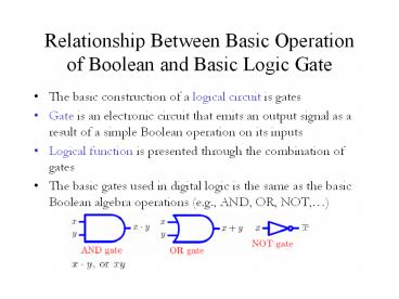
- The basic construction of a logical circuit is
gates - Gate is an electronic circuit that emits an
output signal as a result of a simple Boolean
operation on its inputs - Logical function is presented through the
combination of gates - The basic gates used in digital logic is the same
as the basic Boolean algebra operations (e.g.,
AND, OR, NOT,)
2
- The package Truth Tables and Boolean Algebra set
out the basic principles of logic.
the symbols, algebra signs and the truth table
for the gates
3
Basic Theorems of Boolean Algebra
1. Identity Elements 2. Inverse
Elements
1 . A A A . A 0
0 A
A A A 1 3.
Idempotent Laws 4. Boundess Laws
A A A A 1 1
A . A A
A . 0 0 5. Distributive Laws 6.
Order Exchange Laws A . (B C) A.B
A.C A . B B . A A
(B . C) (AB) . (AC) A B B
A 7. Absorption Laws 8. Associative
Laws A (A . B) A A (B C) (A
B) C A . (A B) A A . (B . C) (A .
B) . C 9. Elimination Laws 10. De
Morgan Theorem ?
?????? ? ?
A (A . B) A B (A B)
A . B ?
????? ? ? A .
(A B) A . B (A . B) A B
4
Exercise 1
- Apply De Morgan theorem to the following
equations - F V A L
- F A B C D
- Verify the following expressions
- S.T V.W R.S.T S.T V.W
- A.B A.C B.A A.B A.C
5
Relationship Between Boolean Function and Logic
Circuit
Boolean function ? Q AB B (NOT A AND
B) OR B
Logic circuit
Q
B
6
Relationship Between Boolean Function and Logic
Circuit
- Any Boolean function can be implemented in
electronic form as a network of gates called
logic circuit
A.B AB
7
G A . (B C D)
G A . (B C D)
8
Truth Table
9
Produce a truth table from the logic circuit
0 0 1 0 0
0 1 1 1 1
1 0 0 0 0
1 1 0 0 1
10
Exercise 2
- Build a truth table for the following Boolean
function
G A . (B C D)
11
Karnaugh Map
- A graphical way of depicting the content of a
truth table where the adjacent expressions differ
by only one variable - For the purposes simplification, the Karnaugh map
is a convenient way of representing a Boolean
function of a small number (up to four) of
variables - The map is an array of 2n squares, representing
all possible combination of values of n binary
variables - Example 2 variables, A and B
B
B
B
1
0
A
A
A B A B
A B A B
00 01
10 11
0
A
1
12
4 variables, A, B, C, D ? 24 16 squares
CD
AB
C D
C D
C D
C D
0000 0001
0100
1100
1000
A B
A B
A B
A B
13
00 01 11 10
AB
- List combinations in the order 00, 01, 11, 10
A B
A B
A B
A B
C
000 010 110 100
001 011 111 101
C
0 1
C
0 1
C
AB
C
000 001
010 011
110 111
100 101
A B
00 01 11 10
A B
A B
A B
14
How to create Karnaugh Map
Truth Table
A B C F
0 0 0 1
0 0 1 0
0 1 0 0
0 1 1 1
1 0 0 1
1 0 1 1
1 1 0 0
1 1 1 0
- Place 1 in the corresponding square
Karnaugh Map
BC
B C
B C
B C
B C
0 0 0 1 1 1 1 0
A
1 1
1 1
0
A
1
A
15
Karnaugh Maps to Represent Boolean Functions
0 0 0 1 1 1 1 0
AB
A B
A B
A B
A B
1 1
16
- Group the adjacent squares
- Begin grouping square with 2n-1 for n variables
- e.g. 3 variables, A, B, and C
- 23-1 22 4
- 21 2
- 20 1
BC
B C
B C
B C
B C
0 0 0 1 1 1 1 0
A
1 1
1 1
0
A
1
A
17
3 variables 23-1 22 4 22-1 21 2 21-1
20 1
BC
B C
B C
B C
B C
0 0 0 1 1 1 1 0
A
1
1 1 1 1
0
A
1
A
18
4 variables, A, B, C, D ? 24-1 23 8
(maximum) 22 4 21 2 20 1 (minimum)
CD
AB
01
00
10
11
1 1
1
1
1 1 1
00
01
11
10
BD
F
19
The following diagram illustrates some of the
possible pairs of values for which simplification
is possible
20
Karnaugh Map
Boolean Function
Logic Circuit
21
Exercise 3
Transform the following truth table to Karnaugh
Map and find the Boolean function
Recommended
CrystalGraphics Presentations


