
Reference Models - PowerPoint PPT Presentation
Title:
Reference Models
Description:
The network authenticates the SIM in the mobile terminal using ... Office Central Office Each phone user ... restrictions support for cellular ... – PowerPoint PPT presentation
Number of Views:216
Avg rating:3.0/5.0
Title: Reference Models
1
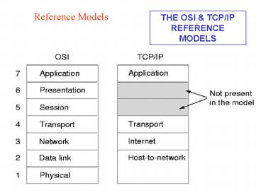
Reference Models
THE OSI TCP/IP REFERENCE MODELS
2
Public Switched Telephone Network (PSTN)
- The PSTN includes a number of transmission links
and nodes - Customer Premises Equipment (CPE) the
equipment that is located at the customer site to
transmit and receive user information and
exchange the control information with the
network, it includes PBXs key telephone systems,
and single line telephones. - Switching nodes interconnect transmission
facilities at various locations and route traffic
through a network.
3
Public Switched Telephone Network (PSTN)
(Continued..)
- Transmission nodes provide communication paths
that carry user traffic and network control
information between the nodes in the network,
include the transmission media, transport
equipment, amplifiers and/or repeaters,
multiplexers and - Service nodes handle signaling, which is the
transmission of information to control the setup,
holding, charging, and releasing of connections,
as well as the transmission of information to
control network operations and billing (SS7)
4
PSTN Architecture
International Gateway
Long-haul Network
Central Office
Central Office
PBX
Central Office
Individual User station lines, or Extensions
Toll switch (For routing calls to or from other
cities)
- Each phone user (subscriber) has a direct
connection to a switch in the central office.
This is called the local loop - The local loop has a length of 1 10 km
- The switches in the central office are called
(local) exchange - A company which provides local telephone service
is called a local exchange carrier (LEC)
5
How is voice transmitted?
- Voice can be transmitted in two ways
- Analog voice transmission each voice channel is
allocated a bandwidth of 3.5 kHz - Digital voice transmission analog voice stream
is converted in a digital stream - Standard scheme for voice call Obtain 8000
samples per second, each with length 8 bit
6
How is voice transmitted?
- Until 1960s
- Entire telephone network is analog
- Frequency division multiplexing
- Today
- The local loop is analog.
- The rest of the network is digital (based on TDM)
- All digital When do we get an all digital
network? - ISDN (Integrated Services Digital Network ) is an
all digital circuit-switching technology. ISDN is
available since the early 1990s (in Europe) or
mid-1990s (US). No wide deployment in US - Another all digital but not circuit switched -
telephony solution is IP telephony.
7
All Analog telephone network
Sub- scriber
Sub- scriber
Telephone Switch
Telephone Switch
Sub- scriber
Sub- scriber
- The telephone switch bundles (multiplexes)
multiple voice calls on a high-bandwidth link - The multiplexing method is FDM
8
Analog local loop / digital network
Sub- scriber
Sub- scriber
Telephone Switch
Telephone Switch
1-byte voice samples
Sub- scriber
Sub- scriber
- The first telephone digitizes a voice call (8000
8-bit samples per second) - Switching method is TDM.
- - Switch bundles multiple calls, by interleaving
samples in time. Each receives one 8-bit slot
every 125µs
9
PBX
Long-haul Network
Central Office
Central Office
PBX
Central Office
Toll switch
- A PBX (Private Branch Exchange) is telephone
system within an enterprise that switches calls
within the enterprise on local lines, while
allowing all users to share a certain number of
external lines to the central office. - The main purpose of a PBX is to save the cost of
requiring a line for each user to the telephone
companys central office.
10
The long-haul network
Long-haul Network
Central Office
Central Office
PBX
Central Office
Toll switch
- Toll or backbone switches provide long-distance
connectivity over long distance trunks. - There are only about 500 toll switches in the
united states. Each toll switch can run more than
100,000 simultaneous phone calls
11
Signaling
- Signaling exchange of messages among network
entities - to enable (provide service) to connection /
call - Or the communication necessary to set up a call
from one - subscriber to another
- Before, during, after connection/call
- call setup and tear down
- call maintenance
- measurement, billing
- Between
- end user lt-gt network
- network element lt-gt network element
- end user lt-gt end user
12
Telephone network services
- point-to-point POTS calls
- special telephone numbers
- 800 (888) number service free call to customer
- numbers for life
- caller ID
- calling card / third part charging
- call routing (to end user) prespecified, by
time-of-day - follow me service allows you to select a
temporary alternate phone on campus to receive
your forwarded calls. - incoming/outgoing call restrictions
- support for cellular roaming home number
routed to current cell location
13
Intelligence in the network
- Telephone companies are looking for providing
intelligent services to their subscribers
forward, block, reverse the call charges and
record messages. - Network programmability.
- Competence by delivering value-added services
- This competence led to the standardization of
intelligent network architecture. - SS7 Metanetwork for signaling.
14
SS7 Network Elements
- Signaling points (SPs) network equipment that
can send or receive signaling messages. - Signaling Links (SLs) links that carry
signaling messages ( 56-Kbps or 64-Kbps) - Signaling Transfer points (STPs) intermediate
nodes that route signaling messages from one
place to another.
15
SS7 Network Elements
SP
SP
SL
SL
SL
STP
STP
SL
SL
STP
STP
SP
SP
Bearer Connection
Network 1
Network 2
16
SS7 Protocol Stack
Telephony User Part (TUP)
ISDN User Part (ISUP)
IN Application Part (INAP)
Mobile Application Part (MAP)
Orientation, Administration, and Management Part
(OAMP)
Transaction Capabilities Application Part (TCAP)
Signaling Connection Control Part (SCCP)
Message Transfer Part (MTP) 3
Message Transfer Part (MTP) 2
Message Transfer Part (MTP) 1
17
(No Transcript)
18
SS7 Protocol Stack (Cont.)
- Message Transfer Part 1 (MTP1) Contains
hardware and firmware resources (Network Cards,
Transceivers, and Cables). - Message Transfer Part 2 (MTP2) Responsible for
secure transaction of messages between two
signaling points. - Message Transfer Part 3 (MTP3) Responsible for
routing (Through STP). - Telephony User Part (TUP) Describes the
signaling messages for the setup of calls and
connections in analog telephony networks. - ISDN User Part (ISUP) Describes the signaling
messages for the setup of calls and connections
in Digital networks.
19
SS7 Protocol Stack (Cont.)
- Signaling Connection Control Part (SCCP) Sets
up and manages signaling connections, using MTP3
to route messages reliably from one node to
another. - Supports both Connection-Oriented and
Connectionless signaling contexts. - Carries the information that STPs need to
perform global title translation. (800 numbers,
and number portability) - Transaction Capabilities Application Part
(TCAP) allows signaling nodes to do
transactions. (e.g. Database access). It contains
two types of information 1. Transaction Portion
(starting and ending transactions maintains the
state of the dialog). - 2. Component portion (carries the actual protocol
queries and responses).
20
SS7 Protocol Stack (Cont.)
- A TCAP message can carry the signaling message of
other protocols in the component portion - Operation, Administration, and Management Part
(OAMP) verification network routing Database and
diagnosing link problems. - Mobile Application Part (MAP) Responsible for
Mobility management, GSM networks. - IN Application Part (INAP).
21
- SS7 provides a secure data network for signaling
messages. - It is easy to add special processing nodes for
call processing. - SCP service control points allows an operator
to install and manage services like call
forwarding, and call blocking
22
IN Standardization Implementation
- Problems
- 1. Framework expanding all the time by nature.
- 2. Telephony switches offer more and more
features with every release and new network. - 3. Technology such as GSM and the Internet are
constantly changing the environment that IN
operates in. - Assumptions
- Upward compatibility
- IN collection of dedicated computers that
perform special control functions. - IN software architecture that runs services.
- IN set of nodes as it is a software framework.
23
IN Standardization Implementation (Cont.)
ITU -gt INCM look for the IN from different
angles.
2. Global Functional Plane (GFP) Identify the
building blocks out of which to construct
services. (Looks at services from the providers
point of view). Describes the software components
that a service providers must deploy to assemble
services.
1. Service Plane (SP) Describes what features a
service is composed of. E.g. the freephone
service consists of two features 1. One
number feature routes incoming calls to a single
external number from different telephones. 2.
Reverse Charging The owner of the freephone
number Pays instead of the caller.
3. Distributed Functional Plane (DFP) Reflects
the distribution of functions. It is the result
of interactions between switches that use
protocols to decide how to route the call from
source to destination
4. Physical Plane (PP) Allocates functions to
physical locations or machines. E.g. 1. SSP
contains the switch, CCF, and SSF. 2. SCP
contains SCF. 3. SMP contains SMF. 4. SDP cont.
DB, SDF. 5. IP impl. SRF.
24
IN Standardization Implementation (Cont.)
Alcatel SCP Architecture
Memory Channel
BEP
BEP
BEP
BEP
BEPs Run the actual service software
FEPs Terminate the SS7 connections and run the
SS7 Protocols
Ethernet
DB
FEP
FEP
Service Control Point
SS7 Network
FEP BEP selected for three reasons 1.
Performance
2. Scalability 3. Reliability
25
IN and the Internet
- Many operators and manufacturers already started
making their IN platforms Internet ready with
proprietary solutions.
- IP, the Internet, and the Web
- Routers and Gateways hubs, bridges, routers,
gateways, firewalls. - Connecting to the Internet using modems via an
ISPs. - ISDN
- ADSL, VDSL, and DHN
- Satellite Networks, LEO
- Cellular Networks GSM, GPRS
26
IN and The Internet
Intelligence on the Internet
- The internet is a network of networks.
- Not administered by a central operator
- Invented for data communication not for voice
communication - Communications achieved by the routing packets
of data - IP addresses and telephone numbers are differ on
format, scope, and the way that they are
assigned. - IP Networks have almost the intelligence on the
application layer - The Features in IN are centralized and
controlled from the SCF. In the Internet they are
completely distributed through the network. - Some IN features do not make sense in the
Internet freephone, calling card calls - All of this changes when we use the Internet
Infrastructure for telephony.
27
IN and The Internet
Intelligence on the Internet
Voice, Video, and Multimedia over the Internet
- TCP/IP Designed for communicating data (files,
e-mail, web pages) between servers and clients.
It breaks the data up into packets and routs them
to their destination, where they are reassembled
and passed to the receiving application. - Voice and video could be translated into bits
using codecs, IP routers should be able to deal
with it as they do the routing of a file or a web
page. - H323 is the standard for providing Voice and
Multimedia services over packet networks. Can
involve the following components - Gateways, Gatekeepers (address translation, call
authorization, accounting and billing, call
management), Multipoint Control Units.
28
The Mobile Dimension
- Three types of mobility in telecommunications
- Terminal mobility the terminal is connected to
the network via radio interface and can move
around freely (e.g. cordless and cellular phones) - User mobility the user can move from one
terminal to another and register for incoming and
outgoing calls to be made to and from this
terminal. (e.g. calling cards) - Service mobility the portfolio of services that
a user has subscribed to follows the user as he
or she roams to different networks (the concept
of exporting content and service to visited
location)
29
The Mobile Dimension
Cellular Networks
- Types of Terminal Mobility Networks
- Cordless DECT, CT2,
- Cellular GSM, DAMPS,
- Satellite LEO EUTELSAT,
- GEO SKYBRIDGE,
A cellular network employs many radio cells of
limited coverage to cover a large area that gives
the following advantages 1. A mobile phone is
always close to a network transceiver, needs less
transmission power. 2. channels can be reused in
different cells, the capacity of network
increases as the cell size shrinks.
30
The Mobile Dimension
Cellular Networks Generations
First Generation (1G) 1980 analog cellular
networks (e.g. AMPS USA, NMT Scandinavia,
C-450 Germany, RTMS - France). Second
Generation (2G) 1990 digital transmission,
higher capacity, Better standardization (e.g.
GSM, D-AMPS, IS-95, PDC) . Third Generation (3G)
2000 Multimedia communications, Mobile
Internet, Capacity services (e.g. GPRS, UMTS)
31
The Mobile Dimension
GSM
GSM radio interface is a mix of Time- and
Frequency-division Multiple Access (TDMA and
FDMA) with Frequency Division Duplex (FDD).
Frequency Channel
0.58ms
200kHz
94
1001 0101 1101
93
1111 1100 0110
92
1 2 3 4 5 6 7 8 1 2 3 4 5 6 7 8 1 2 3 4
Time Slot
Time
32
The Mobile Dimension
GSM Architecture
- A GSM network consists of three components
- Mobile Station (MS) GSM network terminals, they
connect to the network through a radio interface
and require processing power. - Base Station Subsystem (BSS) consists of a base
station controller (BSC) and base transceiver
stations (BTS). - Network Switching Subsystem (NSS) the core
network part of the GSM, the key component in NSS
is the Mobile Switch Center (MSC) A Visited
Location Register database (VLR) holds the
subscriber data for visiting subscribers A home
Location Register database (HLR) holds the
essential subscriber information including
information about the VLR to which a subscriber
is currently attached.
33
The Mobile Dimension
GSM Architecture (Cont.)
MS
HLR
BSC
BTS
BTS
MSC
To other MSC or other Networks
BSC
BTS
VLR
BTS
Base Station Subsystem
Network Switching Subsystem
34
The Mobile Dimension
Mobility Management and Handover
- Procedures that enable mobile terminal when a
call arrives. - GSM is divided into location areas, each area
covers several radio cells and has a unique
identifier transmitted on a special channel in
all the cells it contains. - Each mobile monitors this channel. When it
detects a change in the broadcast location area
identifier (LAI), the mobile terminal knows it
has crossed into another location areas radio
cell. at that time it requests a location update
from the network.
35
The Mobile Dimension
Mobility Management and Handover (Continued)
- Two ways that a location update can take
place - If the new location area is served by the same
MSC and VLR, then the VLR registers the move. - If the new location area is served by the
another MSC and VLR, then the mobile subscriber
information is moved from the old to the new VLR.
The HLR is also updated so that it can rout all
incoming calls to the new MSC and VLR as follows
36
The Mobile Dimension
Mobility Management and Handover (Continued)
- The mobile terminal moves into a new cell, notice
that the location identifier for this cell is
different, and requests a location update. - The VLR requests the subscriber information from
the HLR. - The HLR sends the subscriber information to the
VLR and registers that the subscriber is now
attached to the new VLR. - The HLR informs the old network of the move and
orders the old VLR to remove the record for this
subscriber.
37
The Mobile Dimension
Mobility Management and Handover (Continued)
4
Location Area A
MSC
VLR
BSC
HLR
3
1
VLR
MSC
BSC
2
Location Area B
Location Update
38
The Mobile Dimension
Mobility Management and Handover (Continued)
Handover When the network and the mobile
terminal perceive a decline in quality of the
current connection, the network will look for a
better channel in a neighboring cell. The mobile
terminal must be detached in real time from the
radio channel of the old cell and attached to the
new channel in the new cell.
39
The Mobile Dimension
GSM Security
- A subscriber identity module (SIM) stores the
GSM subscription. - Each subscription has a unique identifier, the
international mobile subscriber identity (IMSI). - The dialed number is called the mobile station
ISDN number (MS-ISDN). - The HLR stores the mapping from MS-ISDN to IMSI.
- The network authenticates the SIM in the mobile
terminal using a secret key algorithm. The
visited network will request a location update by
sending the mobile station roaming number (MSRN)
to the HLR.
40
The Mobile Dimension
GSM Security (Continued)
- The MSRN is an identifier composed of the IMSI
and the LAI of the cell where the mobile terminal
is located. - The VLR assigns a temporary identifier for the
mobile terminal that is locally unique, the
temporary mobile station identifier (TMSI). It is
much shorter than IMSI and prevents the IMSI from
being sent over the air frequently. - The VLR stores the relationship between IMSI and
TMSI, and also keep track of the location area of
the mobile terminal in the form of the MSRN - when the call is established, the exchange of
the digital voice is encrypted using the same
secret key as for authentication, but using a
different algorithm.
41
The Mobile Dimension
GSM Security
HLR
VLR
MS-ISDN IMSI MSRN
IMSI TMSI MSRN
IMSI SIM
BSC
MSC
BTS
TMSI
MS
Visited Network
Home Network
Use of Identifiers in GSM
42
The Mobile Dimension
GSM Connection Services
- GSM provides the following services
- Basic voice (using 13 kbps codec)
- Half - rate voice (using 6.5 kbps codecs)
- Circuit Switched data connection (9.6 kbps)
- SMS (Store-and-forward Messages of 160
characters) - Cell broadcast (93 characters)
- USSD transfer of service data between mobile
terminal and HLR.
43
The Mobile Dimension
General Packet Radio Service (GPRS)
- GPRS deployed by operators that already have a
GSM network it is implemented as an extension of
the existing GSM infrastructure. - GPRS Radio Interface
- GPRS occupies free time slots only when a packet
is sent or received in a dynamic way. - The maximum number of time slots that a terminal
can handle is called mutlislot class of the
terminal. It depends on the processing power and
radio interface hardware in the terminal.
44
The Mobile Dimension
GPRS Radio Interface
Frequency Channel
0.58ms
200kHz
94
1001 0101 1101
93
1111 1100 0110
92
1 2 3 4 5 6 7 8 1 2 3 4 5 6 7 8 1 2 3 4
Time Slot
Time
Mobile 1 sends on channel 93 in time slot 4
Mobile 2 sends on channel 92 in time slot 2
GPRS packet transmission in free time slots
45
The Mobile Dimension
GPRS Radio Interface (continued)
- Many terminals support more slots for the
downlink than for the uplink. - Most terminal multislot classes commercially
available are 41, 31, , and 22. - The data rate depends on the number of slots and
the coding scheme employed to map the data
packets on the channel bit stream. - The most frequently used scheme offers 13.4 kbps
per time slot.
46
The Mobile Dimension
GPRS Architecture
PTSN, ISDN, or GSM
MSC
GMSC
Circuit
Switched
VLR
BSC
HLR
BTS
PCU
MS
SGSN
Internet
GGSN
IP
GPRS-Specific infrastructure
47
The Mobile Dimension
GPRS Architecture
- Installing GPRS requires software updates in the
BTS, MSC, VLR, and HLR. - The BSC needs to extend with a Packet Control
Unit (PCU), which inserts the packet data traffic
into the GSM channel structure. - GPRS core network contains
- The serving GPRS support node (SGSN), which routs
the packets to and from the mobile terminals. - The Gateway GPRS support node (GGSN), which acts
as the gateway to the external packet network.
48
The Mobile Dimension
GPRS Mobility Management
- The GPRS network is divided into routing areas,
to find a compromise between notifying the
network of each cell change and the broadcasting
of packets for each subscriber to the whole
network. - The routing area is the same as, or a subset of
, a location area. This gives the following
advantages to the GSM-GPRS subscribers - GSM updates automatically imply routing area
updates. - An incoming GSM call can be paged in the GPRS
routing area. Which is smaller than a location
area that means less use of radio resources for
paging.
49
The Mobile Dimension
GPRS Mobility Management
- ATTACHMENT AND DETACHMENT PROCEDURE
- Before a mobile station can use GPRS services,
it must register with an SGSN of the GPRS
network. The network checks if the user is
authorized, copies the user profile from the HLR
to the SGSN, and assigns a packet temporary
mobile subscriber identity (P-TMSI) to the user.
This procedure is called GPRS attach. - For mobile stations using both circuit switched
and packet switched services it is possible to
perform combined GPRS/IMSI attach procedures. The
disconnection from the GPRS network is called
GPRS detach. It can be initiated by the mobile
station or by the network (SGSN or HLR).
50
The Mobile Dimension
GPRS Connection model
- A GPRS subscriber can be in one of the following
states
State model of a GPRS mobile station.
51
The Mobile Dimension
GPRS Connection model (Continued)
- In IDLE state the MS is not reachable.
Performing a GPRS attach, the MS gets into READY
state. With a GPRS detach it may disconnect from
the network and fall back to IDLE state. All PDP
contexts will be deleted. - The STANDBY state will be reached when an MS
does not send any packets for a longer period of
time, and therefore the READY timer (which was
started at GPRS attach) expires. - An MS in READY state informs its SGSN of every
movement to a new cell.
52
The Mobile Dimension
GPRS Connection model (Continued)
- For the location management of an MS in STANDBY
state, a GSM location area (LA) is divided into
several routing areas (RA). In general, an RA
consists of several cells. The SGSN will only be
informed when an MS moves to a new RA cell
changes will not be disclosed. To find out the
current cell of an MS in STANDBY state, paging of
the MS within a certain RA must be performed.
53
The Mobile Dimension
GPRS Connection model (Continued)
- For MSs in READY state, no paging is necessary.
Whenever an MS moves to a new RA, it sends a
routing area update request to its assigned
SGSN. The message contains the routing area
identity (RAI) of its old RA. The base station
subsystem (BSS) adds the cell identifier (CI) of
the new cell, from which the SGSN can derive the
new RAI.
54
The Mobile Dimension
GPRS Connection model (Continued)
To exchange data packets with external PDNs after
a successful GPRS attach, a mobile station must
apply for one or more addresses used in the PDN,
e.g., for an IP address in case the PDN is an IP
network. This address is called PDP address
(Packet Data Protocol address). For each session,
a so-called PDP context is created, which
describes the characteristics of the session. It
contains the PDP type (e.g., IPv4), the PDP
address assigned to the mobile station (e.g.,
129.187.222.10), the requested QoS, and the
address of a GGSN that serves as the access point
to the PDN. This context is stored in the MS, the
SGSN, and the GGSN. With an active PDP context,
the mobile station is visible for the external
PDN and is able to send and receive data packets.
The mapping between the two addresses, PDP and
IMSI, enables the GGSN to transfer data packets
between PDN and MS. A user may have several
simultaneous PDP contexts active at a given time.
55
Distributed Intelligence
Parlay OSA
- Intelligent networks were originally designed
for telephony networks. - Services are controlled and managed centrally by
the network operator. - The IN model doesnt seem prepared to deliver
value-added services in an environment that is
becoming heterogeneous and competitive. - Several industry initiatives sought to develop
more state-of-the art software architectures for
service deployment and operation.
56
Distributed Intelligence
Parlay OSA (cont.)
- Parlay OSA appear to be the technologies that
are leading the way in the evolution of IN the
key concept in both is the distribution of
service control.
Parlay Concept
- The network provider is responsible for
deploying, operating, and managing services. - The idea of Parlay is to open this interface to
third parties, so that others beside the network
operator can create and deploy services.
57
Parlay Concept
Parlay
SMF
Third-party application
Intelligent network
Proprietary interface
Public interface
SCF
Proprietary interface
SSF
PSTN operator
58
Distributed Intelligence
Parlay Concept (cont.)
- The Parlay interface also allows access to other
network functionalities, such as messaging,
charging, QoS negotiation, and mobility
management. - Network access to third-party applications is
subject to authentication and authorization. - Parlay allow the network provider to set
different privilege levels (e.g. some third-party
applications can be allowed to receive only
notifications from the network while others can
control calls and connections) - Parlay also provides facilities for
nonrepudiation.
59
Distributed Intelligence
Parlay Business Model
Subscription
QoS Connectivity Management
Enterprise Administration
Trust and Security management Discovery Integrity
management
Call Control User Interaction Messaging Mobility
Client Application
Parlay Service
Parlay framework
Service Provider
Framework provider
Service factory
Registration
(Not in specified Parlay)
60
Distributed Intelligence
Parlay Business Model
- Client Application the third-party application
that accesses network features through Parlay
interface. (deployed and operated by the
enterprise administration) - Framework Interfaces offer all support
functions for Parlay, in particular security and
management features (administered by the service
provider) - Service Interfaces offer access to network
features, such as call control, messaging, and
mobility management (administered by the service
provider)
61
Distributed Intelligence
Parlay Business Model
- Parlay wanted to ensure complete flexibility in
mapping Parlay business roles into real-world
physical entities. - Parlay allows the provider of the framework
interface to be different from the provider of
the service interface.
From Parlay to OSA
- At the same time that Parlay began gaining
momentum, 3GPP and ETSI were working on the OSA
interfaces for UMTS.
62
Distributed Intelligence
From Parlay to OSA
- Because Parlay and OSA are so similar, most
manufacturers have been combining both interfaces
in one product. - There remains some differences between the two
- Parlay specifies only a business model and a set
of interfaces. - Parlay very explicitly refrains from specifying
any requirements on the implementation of the
interfaces. - Parlay is generic and stand-alone interface
specification. While - OSA Specifies more than just an interface and
must be seen as a service architecture. - ETSI makes recommendations for mapping OSA
interface to network protocols like MAP CAP. - OSA is an integral part of the service
architecture for UMTS.
63
Distributed Intelligence
OSA interfaces
- OSA and Parlay consist of 10 main interface
groups
Interface Short description
Framework Overall security, integrity, and management framework
Call control Setting up, releasing, and managing calls, conferences, and multimedia connections notifications of call- and connection-related events.
Data session control Setting up, releasing and managing data sessions
User interaction Play or display messages and retrieve user input
Mobility Notifications of user location and user status
Generic messaging E-mails, voice mails, SMS
Terminal capabilities Interrogating a terminal for its capabilities
Connectivity management Negotiation and management of QoS and service Lev agr IP
Account management Creating, deleting, and modifying subscriber accounts
Charging Reservation and charging of units of volume or money
64
Distributed Intelligence
OSA interfaces
- Parlay offers two extra interfaces that are not
parts of OSA - a. Policy Management allows for the creation
and management of policy classes and their
parameters to provide application service
providers with the possibility of defining
service-level agreements (SLAs) - b. PAM. Allows subscribers and terminals in the
network to exchange information about presence
and availability (buddy lists and instant
messaging). - OSA interfaces are defined as a set of object
types (classes) class definitions follow an
inheritance hierarchy.
65
Distributed Intelligence
OSA interfaces
- Each of the OSA interfaces is specified (in UML
and IDL) in four parts - 1. Class diagrams. Provide an overview of the
inheritance structure of the interface, its
classes and operations. - 2. Sequence diagrams. Show key examples of use of
the interface in the form of UML message sequence
charts. - 3. Interface specifications. Provide the formal
definition of the interface - 4. Data definitions. Provide formal data-type
definition in IDL.
66
Distributed Intelligence
General Interface Structure
- OSA defines two object classes for each
interface on the network side - IpltInterfacegt - is the actual interface that
offers operations to control resources in the
network. - IpltInterfacegtmanager - is a management interface
that that contains the operation to start and
manage an instance of IpltInterfacegt. Its also
used to request server-related event
notifications like overload conditions. - The client application also has to implement two
object classes for each interface - 1. IpAppltInterfacegt - is a client-side
interface that contains operations for receiving
results and notifications from the IpltInterfacegt
interface. - 2. IpAppltInterfacegtmanager - is an interface for
receiving results and notifications from the
IpltInterfacegtmanager interface.
67
Distributed Intelligence
OSA Interface Structure
OSA server
Application
IpltInterfacegtManager
IpAppltInterfacegtManager
Notifications
Creates, manages
IpltInterfacegt
IpAppltInterfacegt
Notifications, results
68
Distributed Intelligence
General Interface Structure
- These client-side interfaces are often called
callback interfaces they are just like
procedure calls in programming languages such as
Pascal, operations on objects are synchronous a
client application that requests an operation on
an object has to wait for this operation to
finish and send back the result. - By putting a callback interface on the client it
is possible to decouple the delivery of the
result from the request. - Callbacks are used to allow asynchronous
communication with synchronous operations.
69
Distributed Intelligence
OSA call-control interface
- OSA offers several interfaces for call control,
some of these interfaces consist of several
classes with an inheritance relation. - The figure below shows the inheritance structure
(the main classes defined at the server side) - A new object class is defined in a terms of an
existing one by inheriting and extending the
operations of the parent class
70
Distributed Intelligence
OSA call-control interface (Server side)
0n
1
IpMultiPartyCall
IpCallLeg
0n
1
1
IpMultiMediaCall
IpMultiMediaCallLeg
0n
0n
0n
IpMultiMediaCallLeg
1
1
IpConfCall
1
0n
IpSubConfCall
71
Distributed Intelligence
OSA call-control interface
- There are three main types of call defined in
OSA - Multiparty calls calls with zero or more
parties. The connections set up within a call are
represented by call-leg objects (connect and
disconnect call parties within the scope of a
call) - Multimedia calls multiparty calls that allow for
multimedia connections between parties. (can
create and delete multimedia call legs each of
which can have several streams) - Conference calls multimedia calls in which there
exists the possibility of defining additional
relationships between the parties (the chair
party has privileges to add parties, drop
parties, give a party to turn a speak, and
interrupting a speaking party). It is possible to
create subconferences, and to move parties from
one subconference to another
72
Distributed Intelligence
Using OSA
- The complete cycle for using an OSA service
consists of three phases - Authentication before using OSA services, the
application and the OSA framework authenticate
each other (prevents unauthorized access) - Service selection the application selects the
service interface. Request the signing of
agreement before using the interface. - Service use only after the authentication and
service selection the application start using the
actual service.
73
Application
OSA Framework
Initiateauthentication
(1)
Specify an authentication method (e.g., challenge
response)
authentication method
authenticationFramework
(2)
Compute authentication response
Evaluate authentication response
authentication response
authenticationSucceeded
authenticate Client
(3)
Compute authentication response
authentication response
Evaluate authentication response
authenticationSucceeded
obtainDiscoveryInterface
(4)
Create
Discovery
Interface reference
DiscoverServices
Get Profile
Services
74
Using OSA Service Selection Service Agreement
Distributed Intelligence
Application
OSA Framework
Select Service
(5)
Prepare service agreement
SignServiceAgreement
Evaluate agreement
(6)
Signature
SignServiceAgreement
(7)
Evaluate agreement
Signature
Create
Create
(8)
(8)
IpAppCallControlManager
IpCallControlManager
setCallback
(9)
75
Using OSA Call Setup
Distributed Intelligence
IpAppCallControlManager
IpCallControlManager
Create
IpAppCall
(10)
createCall
(11)
Create
IpCall
routeReq
(12)
Party A rings Party A answers
routeRes
(13)
routeReq
(14)
Party B rings Party B answers
routeRes
(15)
76
Distributed Intelligence
OSA Applications
- OSA can bring the following added value
- Third-party service control. Allow the
integration of network features with applications
external to the network. (OSA needed to securely
access the networks features) - Roaming interface. Current roaming agreements
require a high level of trust between the roaming
partners. OSA has a security framework, it offers
roaming between parties that dont have an
established trust relationship.
77
Distributed Intelligence
OSA Applications (Continue)
- Protocol replacement. OSA can provide a standard
programming interface for these network
functions OSA also provides a framework for
features that might be added in the future. - Content billing. The OSA charging interface can
be used to dynamically establish relations
between volume and value.
78
Distributed Intelligence
OSA Applications Example Taxi Dispatcher
- The idea is that when a client calls, his mobile
terminal is automatically located and a program
automatically alerts the nearest taxi. To
implement this service, the taxi dispatcher
subscribes to the following three OSA service
interfaces offered by the mobile network
operator - Call control to automatically notify the taxi
dispatcher of requests for taxis - Mobility to determine the position of the
calling customer and the taxis - Generic messaging to send a notification to the
nearest taxi.
79
Distributed Intelligence
OSA Applications Example Taxi Dispatcher
(Cont.)
- OSA supports two ways of locating taxis (mobile
terminals) - To ask for the position of all taxis whenever a
customer calls. - To have the network send periodic positioning
information for each taxi, for example every 5
minutes. - The taxi dispatcher develops an application that
automatically receives a notification when a
customer calls, then locates the customer and
finds the nearest taxi, the program send a short
message to alert the taxi to pick up the client.
This includes the following steps - A customer dials a special number to request a
taxi.
80
Distributed Intelligence
OSA Applications Example Taxi Dispatcher
(Cont.)
- The OSA interface notifies the taxi dispatcher
application of the customers call. Identifies
the calling-party number. - The taxi dispatcher requests location of the
calling party or the (taxis) through the OSA
interface. Forwards it to the MLC. - The network locates the calling party or the
taxis (this may be done periodically). - Receiving the callers coordinates, it looks up
the geographic location in a database and
determines the nearest taxi. - The application sends a short message to the
nearest taxi through the OSA interface to pick up
the customer at the indicated location.
81
Distributed Intelligence
OSA Applications Example Taxi Dispatcher
(Cont.)
Taxi
Taxi
Taxi
Taxi Dispatcher
GMLC
(3)
(4)
(2)
Application
OSA
MSC
(6)
(5)
(6)
SMSC
(1)
Database
Mobile network
82
Telecommunications Information-Networking
Architecture (TINA)
Telecommunications Middleware
- Middleware is software that runs between
machines operating system and the applications. - TINA Business Model
- TINA architecture
- Session model
- TINA Service Architecture
- Computational objects
- Access session
- Service session
- TINA network-resource Architecture
- Computational objects
- Connection establishment
- Federation
83
Telecommunications Middleware
TINA Architecture
Retailer
Service
Service
Service
Consumer
Service Architecture
Terminal Application
Resource Management Architecture
ATM Switch
ISDN Switch
IP Router
Connectivity Provider
84
Telecommunications Middleware
Service session graph
Service Session graph
Contains
Session member
Session relation
Is-a
Is-a
Stream binding
Control relation
Party
resource
85
Telecommunications Middleware
Access session
- The procedure for starting an access session
- When the user requests an access session, the PA
(provider agent) in the terminal contacts the
IA(initial agent) in the network. The address of
the IA is always known to any TINA network. - The IA consults the subscription database,
authenticates the user, and finds the UA(user
agent) for this user. (UA can be in a remote
network). - The UA activates an access session for the user.
The PA in the terminal is linked to the UA for
the duration of the access session and the user
can start using the services.
86
Telecommunications Middleware
Access session
- Through the access session, the user can do any
of the following - Request a list of available services. The UA will
list the services that the user is subscribed to.
- Request the start of a service session. The
access session is always the window through which
services are started. - Receive invitations from other users to join a
service session. - Join a service session that is already active.
- Register remotely at terminals. A user can
request to be registered on a remote terminal for
incoming invitations to join sessions.
87
Telecommunications Middleware
Service session graph
- The TINA service session offers the following
features that allow parties to modify the session
graph - Basic features such as starting, stopping, and
suspending a session - Multiparty features adding or dropping a party
in a session - Stream-binding features adding or dropping a
stream binding to a party in the session - Voting features voting among parties in the
session (permission of a new party to join the
session) - Control features for modifying control relations
between parties (transferring chairmanship of a
videoconference).
88
Telecommunications Middleware
TINA network-resource Architecture
- TINA sets up connections in three main steps
- Negotiation. The communication session queries
all involved terminals and network entities for
their capabilities, and selects a set of common
capabilities that will allow the connection to be
set up. - Reservation. The communication session asks all
involved terminals and network entities to
reserve the selected capabilities. - Commitment. If all involved terminals and
networks confirm the reservation of the necessary
resources, the communication session will then
order them to commit the resources and the
connection is set up.
89
Telecommunications Middleware
TINA network-resource Architecture
Service session
Retailer
Terminal Application
Consumer
Negotiate
TCSM
CSM
Connectivity provider
CC
M
Reserve and commit
TLA IP
LNC IP
Terminal resources
Network resources
90
Telecommunications Middleware
Connection Establishment
- The negotiation phase consists of the following
steps - The CSM queries the TCSM of each terminal for the
terminal capabilities. The terminals respond by
giving a list of capabilities they can support (4
slot GPRS) - The CSM matches the terminal capabilities listed
by each terminal, and defines the common set of
capabilities that will allow the requested
connection to be established. - The CSM tells the TSCM which capabilities are
needed and asks the TSCM to select the necessary
resources in the terminal. - The TCSM asks the TLA to identify the terminal
end points that correspond to the requested
capabilities. (GSM channels, IP addresses) - The selected end-point coordinates are propagated
back to the CSM.
91
Telecommunications Middleware
Negotiation phase in TINA connection setup
TCSM
TLA
TCSM
TLA
CSM
Query capabilities
(1)
Terminal capabilities
Query capabilities
Terminal capabilities
CSM selects common capabilities
(2)
Select capabilities
Select end points
Select capabilities
Select end points
(4)
(3)
TLA selects terminal end points that fit the
requested capabilities
TLA selects terminal end points that fit the
requested capabilities
End points
End points
End-point address
End-point address
(5)
Terminal A
Terminal B
92
Telecommunications Middleware
Connection Establishment
- The reservation phase consists of the following
steps - The CC contacts the LNC for each subnetwork
involved, and asks them to set up the necessary
connections within their domain. - The LNC asks the terminal to reserve the
resources negotiated in the previous steps. The
LNC also reserves the necessary network
resources. - If the selected terminal end-points are
available, the LNC asks the TLA to associate them
with physical resources in the terminal. - The TLA asks the TCSM to link the terminal
applications to the physical ports in the
terminal that will terminate the connection.
93
Telecommunications Middleware
Reservation phase in TINA connection setup
TCSM
TLA
TCSM
TLA
LNC
CC
LNC
Set up connection
(1)
Set up connection
(2)
Reserve resources
Reserve resources
(2)
Terminal reserve resources
Network reserve resources
Network reserve resources
Terminal reserve resources
Terminal end-point settings
Terminal end-point settings
Associate end points
Associate end points
(3)
(3)
Associate end points
(4)
Associate end points
(4)
The TLA associates end points with terminal
ports, and the TCSM links the application to them
The TLA associates end points with terminal
ports, and the TCSM links the application to them
OK
OK
OK
OK
Terminal A
Terminal B
Network A
Network B
94
Service Creation
From SIBs to Objects
- The key issue is how to conduct business with
the new architectures. - Telecommunications business is determined by the
services and offered and their price. - Service creation is all about software
engineering. - Telecommunications software is complex,
concurrent, must be reliable and deliver high
performance. - The INCM recognizes the need for efficient
creation of new services. It defines services as
compositions of features, which are composed out
of elementary building blocks, SIBs. - An IN service-creation environment allows even
inexperienced service engineers to create
services by clicking together elementary building
blocks in a plug-and-play fashion.
95
Service Creation
From SIBs to Objects
Begin
Play announcement Get calling card ID from user
(1)
User Interaction
Look up calling card in database
Service data management
(2)
Play announcement Get PIN from user
User Interaction
(3)
No match
Validate PIN against card data
Compare
(4)
Play error announcement
Charge communication to calling card
Charge
User Interaction
(5)
(6)
Return to BCP Release call
Return to BCP Continue setting up the
call
Continue
Clear call
96
Service Creation
From SIBs to Objects
- The calling card service shows the SIB flow and
performs the following steps - A message is played to the user, asking for the
calling-card ID, and user input is received in
the form of DTMF tones. - The calling card data is retrieved from the
database using the calling-card ID input by the
user in the previous step. - A message is played to the user, asking for the
PIN code, and user input is received in the form
of DTMF tones. - The PIN provided by the user is verified against
the PIN on the card. - If the PIN is correct, the call is charged to the
calling card and the call setup continues. - If the PIN incorrect (card number or PIN
invalid), an error message is played to the user
and the call is cleared.
Recommended
CrystalGraphics Presentations


