Microprocessors - PowerPoint PPT Presentation
1 / 31
Title:
Microprocessors
Description:
Read Timing Diagram. Srinath RVCE email: srinath_nk_at_yahoo.com. 20. Write Machine Cycle ... 8088, where as the 8086 queue. comprises of 6 bytes. ... – PowerPoint PPT presentation
Number of Views:1255
Avg rating:3.0/5.0
Title: Microprocessors
1
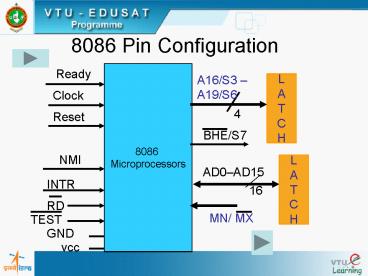
8086 Pin Configuration
8086 Microprocessors
Ready
A16/S3 A19/S6
L A T C H
Clock
4
Reset
BHE/S7
NMI
L A T C H
AD0AD15
INTR
16
RD
MN/ MX
TEST
GND
vcc
2
AD0 - AD15 Address Data Bus
AD0 AD15
Data
Address
3
A19/S6, A18/S5, A17/S4, A16/S3 Address/Status
4
A18/S5 The status of the interrupt enable flag
bit is updated at the beginning of each cycle.
The status of the flag is indicated through this
bus. A19/S6 When Low, it indicates that 8086 is
in control of the bus. During a "Hold
acknowledge" clock period, the 8086 tri-states
the S6 pin and thus allows another bus master to
take control of the status bus.
5
8284 Connected to 8086 Mp
X1
Ready
X2
8086 Microprocessor
CLK
AEN1 AEN2
8284
F/C
Reset
RDY1 RDY2
RES
R
5 V
C
RESET KEY
6
RESET Operation results
7
MN / MX common pins
RQ / GT0
HOLD
HLDA
RQ / G1
LOCK
WR
M / IO
S2
8086 Microprocessors
DT / R
S1
DEN
S0
ALE
QS0
INTA
QS1
Minimum Maximum
8
DMA Operation
9
(No Transcript)
10
(No Transcript)
11
8086 Memory Addressing
Data can be accessed from the memory in four
different ways. They are 8 - bit data from
Lower (Even) address Bank. 8 - bit data from
Higher (Odd) address Bank. 16 - bit data
starting from Even Address. 16 - bit data
starting from Odd Address.
12
(No Transcript)
13
8-bit data from Even address Bank
14
8-bit Data from Odd Address Bank
15
16-bit Data Access starting from
Even - Address
16
16-bit Data Access starting from Odd
Address
17
8086 System Minimum mode
18
8086 System Maximum Mode
19
Read Timing Diagram
20
Write Machine Cycle
21
Comparison of 8086 with the 8088 Microprocessor
SS0
IO/M(S2)
22
- The major differences between
- 8088 and 8086 are outlined below
- The queue length is 4 bytes in the
- 8088, where as the 8086 queue
- comprises of 6 bytes.
- The 8088 BIU will fetch a new instruction to load
into the queue as soon as it finds a byte hole
(space available) in the queue. The 8086 waits
until a 2 byte space is available.
23
- The internal execution time of the instruction
set is affected by the 8-bit interface. All
16-bit fetches and writes from / to memory take
an additional four clock cycles. The CPU is also
limited by the speed of instruction fetch. When
the more sophisticated instructions of the 8088
are being used, the queue has time to fill and
the execution proceeds as fast as the execution
unit will allow.
24
A8-A15 These pins are only address outputs on
the 8088. These address lines are latched
internally and remain valid throughout a bus
cycle in a manner similar to the 8085 upper
address lines. provides the status information in
the minimum mode. This output occurs on pin 34
in minimum mode only. DT/R, IO/M and SS0 provide
the complete bus status in minimum mode.
25
(No Transcript)
26
- BHE has no meaning on the 8088 and has been
eliminated. - IO/ M has been inverted. i.e., (In 8086, this pin
as IO/M)
27
(No Transcript)
28
- Questions
- Explain the operation of the LOCK pin.
- What is the use of QS1 and QS0 pins?
- Explain the operation of the TEST pin and the
WAIT instruction. - What is the purpose of the status bits S3 and S4?
- Compare 8086 and 8088 microprocessors. In what
ways are they similar? In what ways do they
differ?
29
6. What is the purpose of the ALE signal in an
8086 system? 7. What is the major difference
between an 8086 operating in minimum mode and an
8086 operating in maximum mode? 8. Describe the
response of an 8086 when its RESET input is
asserted high. 9. Why are buffers often needed
on the address, data and control buses in a
microprocessor system?
30
10. What are the function of the 8086 DT/and
signals? 11. Explain the difference between a
memory read cycle and an I/O read cycle.
31
(No Transcript)


