
Photovoltaic Systems Engineering - PowerPoint PPT Presentation
1 / 20
Title:
Photovoltaic Systems Engineering
Description:
Reference: Photovoltaic System Design Course manual by Florida Solar Energy Center, Cape Canaveral, Florida Photovoltaic Systems Engineering Test #1 : ... – PowerPoint PPT presentation
Number of Views:193
Avg rating:3.0/5.0
Title: Photovoltaic Systems Engineering
1
Photovoltaic Systems Engineering
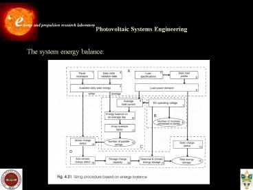
The system energy balance
2
Photovoltaic Systems Engineering
- Input to the sizing procedure
- a) Determination of the energy input - the
incident solar radiation on the panel for a
typical day in every month of the year. - b) Determination of the load demand - the load
profile should be determined by estimating the
times when various appliances will be needed. - Number of series-connected modules
- a) The DC operating voltage of the system VDC
must be specified. - b) The number of modules Ns is determined from
- where Vm is the operating voltage of one module
3
Photovoltaic Systems Engineering
- The number of parallel strings, Np
- This number is directly related to the current
requirement of te load. - a) The equivalent load current is calculated
from the following equation, - where EL (Wh/day) is the typical power
requirement of the day. - b) Nominal current IPV is defined by the AM1.5
radiation at 1kW/m2. - where PSH is peak solar hours, equal to the
number of hours of the standard irradiance
(1kW/m2) which would produce the same
irradiation.
4
Photovoltaic Systems Engineering
The average load current multiplied by the number
of hours in a day the nominal current of the
PV generator multiplied by the number of peak
solar hours The nominal current is equal to the
short-circuit current, Isc c) The number of
modules connected in parallel is then given by
where SF is the sizing factor
5
Photovoltaic Systems Engineering
- Sizing of the storage subsystem
- a) The daily and seasonal charge deficits
calculation - The winter energy deficit, ?E is given by
- where Qyd is the charge deficit in
ampere-hours. - This energy deficit depends on the choice
- of the array sizing factor SF
- b) A further climatic charge deficit is also
added to allow for a number of days of
operation without energy input (lack of
sunshine)
6
Photovoltaic Systems Engineering
Sizing of stand-alone photovoltaic
system Point-sizing approach method It is
designed to meet the load under worst case
isolation conditions, usually in the winter
months for the northern hemisphere. Reference
Photovoltaic System Design Course manual by
Florida Solar Energy Center, Cape Canaveral,
Florida
7
Photovoltaic Systems Engineering
Test 1 Design a stand-alone PV system with
rechargeable batteries to supply electricity for
a rural area residence outside of Tallahassee.
Appliances 10 lights at 40 W each, Refrigerator
(500W), 5 ceiling fans at 45W each, washer
(1500W), Television (200W), Toaster (1500W),
Miscellaneous (1500W). Storage batteries with
bus voltage of 24 V Inverter ac voltage 110
V Inverter efficiency 85 Due Jan 30, 2004
8
Photovoltaic Systems Engineering
COE PV Array Characteristics
9
Photovoltaic Systems Engineering
Grid-connected photovoltaic systems Energy
storage is not necessary in this case
10
Photovoltaic Systems Engineering
COE PV Array Characteristics
11
Photovoltaic Systems Engineering
COE PV Array Characteristics
12
Photovoltaic Systems Engineering
COE PV Array Characteristics
13
Photovoltaic Systems Engineering
PV Industrialization
14
Photovoltaic Systems Engineering
Applications of large scale PV projects
SAN FRANCISCO SOLAR POWER, USA In 2001, two
proposals to install renewable energy systems in
San Francisco were ratified. Construction of a
50MW solar power facility is due to begin in
Spring 2003. This will come from 140-250
photovoltaic acres of panels on commercial,
residential and government rooftops. Another
10-12MW of solar power will come from an
agreement linked to 30MW of wind power and
costing 100 million. This involves photovoltaic
panels being fixed to city facilities and
buildings. Together, these two propositions will
provide electricity for 60,000 homes in San
Francisco. The plant will be six times larger
than the world's largest solar facility,
Sacramento Municipal Utility District, and will
feed power directly into the network. The plan
will cut greenhouse emissions from the area by
around 1, and provide 10 of the city's
electricity in the daytime, and 5 at night (peak
load). The 'peaker' plant will be designed,
built, operated, maintained and transferred by
Local Power through an agreement with California
Power Authority.
15
Photovoltaic Systems Engineering
Cost of PV generated Energy
16
Photovoltaic Systems Engineering
Photovoltaics under concentrated
sunlight Motivation reduced cost due to small
area of the PV array Concentrators only use the
direct beam light. They are always pointed
towards the sun - sun tracker
The important parameter is the concentration
ratio the ratio of the collector aperture (the
opening through which the solar radiation enters
the concentrator) area to absorber area
increasing ratio means increasing temperature at
which energy can be delivered.
17
Concentrating Collectors
Collector configurations e) Fresnel
reflector f) Array of heliostats with central
receiver Goal Increasing the flux of radiation
on receivers
18
Photovoltaic Systems Engineering
Focusing Systems
19
Photovoltaic Systems Engineering
PV-Trough system at ANU
A photovoltaic/trough concentrator system for the
production of electricity in remote areas has
been developed, in conjunction with Solahart
Industries Pty Ltd. The system is based on
sun-tracking mirrors that reflect light onto a
receiver lined with solar cells. The solar cells
are illuminated with approximately 25 times
normal solar concentration, and convert about 20
of the sunlight into electricity. The balance of
the solar energy is converted into heat, which is
removed via a finned aluminium heat exchanger. A
20 kW demonstration system was constructed in
Rockingham, near Perth (Western Australia).
20
Photovoltaic Systems Engineering
PV Concentrator - EUCLIDES
ITER, IES and BP Solarex have carried out the
project for the installation of the world largest
PV concentration grid connected power plant, the
EUCLIDESTM-THERMI plant. This plant is rated 480
kWp and is composed of 14 parallel arrays, each
84 meters long. The arrays are North/South
oriented and close to the ground. Each array
carries 138 modules and 140 mirrors. The modules
are series connected in each array. The geometric
concentration ratio is x38.2, 1.2 times the one
in the prototype. The mirror technology is based
on metallic reflective sheets shaped with ribs to
the parabolic profile. Three different materials
have been tested to be used as reflective
material. The fully encapsulated receiving
modules are made of 10 concentration LGBG BP
Solarex cells, series connected. The modules are
cooled with a passive heat sink. Every two
contiguous arrays are connected, in parallel, to
one inverter sized 60 kVA. The output voltage at
standard operating conditions is 750 Volts. The
inverter, without intermediate transformer, was
designed and manufactured by ITER. The
concentrating optics are mirrors instead of
Fresnel lenses used previously in all PV
concentration developments. The tracking system
is one axis, horizontal, as it is thought that
the one-axis solutions are cheaper than the
two-axes tracking ones. The concentrating schemes
present a more constant output than the flat
panels, so they might present some advantage in
the value of the electricity produced.
Recommended
CrystalGraphics Presentations


