Airfield Diagram - PowerPoint PPT Presentation
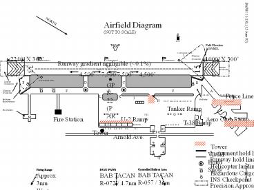
Airfield Diagram
Runway hold lines. H. Helicopter landing pad. Wash Rack. 2. 3 ... Runway gradient negligible ( 0.1%) Fire Station. Tower Visual Blind Spots. Tower. Arnold Ave. ... – PowerPoint PPT presentation
Title: Airfield Diagram
1
NORTH
Airfield Diagram (NOT TO SCALE)
BAFBI 11-250, (15 June 05)
GAT/R
Field Elevation 113 ft MSL
15 ILS Glideslope Antenna
Glideslope Critical Area
1000 X 300
2240 X 300
Wind Sock/Sensor 3
Wind Sock/Sensor 2
Wind Sock/Sensor 1
Runway gradient negligible (lt0.1)
12,000 X 300
33
15
Localizer Critical Area
4,500 7,500
7,500 4,500
33 ILS Glideslope Antenna
E
D
C
B
Localizer Critical Area
GPN-22 (PAR)
C
HCP-1
HCP-2
A
F
F
F
Glideslope Critical Area
Fence Line
L
K
I
H
Hot Brakes Hung Ordinance Hot Armament
Hot Brakes
17A 17 16A 16 15 14 13 12 11 10
Tanker Ramp
J
G
VIP 2 VIP 1
M
U-2 Ramp
Aero Club Ramp
Fire Station
T-38 Ramp
7
U T S R
Q P O N
M L K J
I H G F E
1 1A 2 2A 3 3A 4
5 6 7 8 9
Wash Rack
1
Tower
Arnold Ave.
Tower Visual Blind Spots
Instrument hold lines
Runway hold lines
Helicopter landing pad
HCP-1
Controlled Bailout Area BAB TACAN R-057 / 3nm
PAVE PAWS BAB TACAN R-072 / 4.7nm
Firing Range Approx 3nm West
Hazardous Cargo Pad
Attachment 1
INS Checkpoint
Precision Approach Critical Areas
PowerShow.com is a leading presentation sharing website. It has millions of presentations already uploaded and available with 1,000s more being uploaded by its users every day. Whatever your area of interest, here you’ll be able to find and view presentations you’ll love and possibly download. And, best of all, it is completely free and easy to use.
You might even have a presentation you’d like to share with others. If so, just upload it to PowerShow.com. We’ll convert it to an HTML5 slideshow that includes all the media types you’ve already added: audio, video, music, pictures, animations and transition effects. Then you can share it with your target audience as well as PowerShow.com’s millions of monthly visitors. And, again, it’s all free.
About the Developers
PowerShow.com is brought to you by CrystalGraphics, the award-winning developer and market-leading publisher of rich-media enhancement products for presentations. Our product offerings include millions of PowerPoint templates, diagrams, animated 3D characters and more.


