Basic Instruments - PowerPoint PPT Presentation
1 / 18
Title:
Basic Instruments
Description:
Ammeter: ... Ammeter. Measures current in amperes, milliamperes, microamperes depending on ... Safety: Connect an ammeter is series with a circuit device. ... – PowerPoint PPT presentation
Number of Views:3181
Avg rating:5.0/5.0
Title: Basic Instruments
1
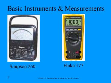
Basic Instruments Measurements
Fluke 177
- Simpson 260
2
Interest
- One of the first meter instruments was used by
the Greeks (0 BC) and was the Sun Dial.
3
Outline
- Types of meter movement
- Types of meters
- Voltmeter
- Ammeter
- Ohmmeter
- Electrical diagrams
4
Basic Multimeters
- A meter is a measuring instrument.
- Ammeter measures current.
- Voltmeter measures the potential difference
(voltage) between two points. - Ohmmeter measures resistance.
- Multimeter combines these functions and others
into a single instrument.
5
Ammeter
- Measures current in amperes, milliamperes,
microamperes depending on the meter scale. - The coil in the meter movement is wound with many
turns of fine wire. - If a large current was allowed to flow the coil,
it would burn it out, so a shunt or alternate
path is provided for current. Most of the current
flows through the shunt. - Safety Connect an ammeter is series with a
circuit device. Never in parallel!
6
Determining Shunt Resistors
- Meter movement requires 1mA for full scale
deflection. The resistance of the coil is 100?.
The ranges of the meter are 0-1mA, 0-10mA,
0-50mA, 0-100mA. - EIR (.001)(100) .1V without a shunt. For
full scale deflection, .1V is required. - A shunt must carry 90 of the current for the
0-10mA scale. - Rs E/I .1/.009 11.1?
- Calculate the other shunt resistors.
7
Voltmeter
- To ensure voltages across the coil never exceed
.1V, multiplier resistors are placed in series
with the meter movement coil using a switch. - Voltage ranges 0-1V, 0-10V, 0-100V, 0-500V
- .1V can be placed across meter at any one time,
therefore a resistor must drop .9V to use a 0-1V
scale. Full scale current deflection is 1mA or
.001A - Rm E/I .9V/.001A 900?
- Calculate multiplier resistors for other scales.
8
Ohmmeter
- Uses non-linier scale zero-infinite.
- Calibrate prior to use for analog meter.
- Check leads at 0? for good lead connections.
- Electrical leads safety story for finger stop.
9
Moving Iron Vane Meter
10
Moving Iron Vane Meter
- Measure either AC or DC.
- It depends on induced magnetism for its
operation. It utilizes the principle of repulsion
between two concentric iron vanes, one fixed and
one movable, placed inside a solenoid. A pointer
is attached to the movable vane. When current
flows through the coil, the two iron vanes become
magnetized with north poles at their upper ends
and south poles at their lower ends for one
direction of current through the coil. Because
like poles repel, the unbalanced component of
force, tangent to the movable element, causes it
to turn against the force exerted by the springs.
11
D'ARSONVAL METER MOVEMENT
- The permanent-magnet moving-coil movement used in
most meters .
12
D'ARSONVAL METER MOVEMENT
- D'Arsonval meter movement is capable of
indicating current in only one direction. - Without a rectifier, or direct current of the
wrong polarity, the meter would be severely
damaged. - Since the pointer will vibrate (oscillate) around
the average value indication, damping is used. - Airtight chamber containing a vane
- The movement of the coil (conductor) through a
magnetic field causes a current to be induced in
the coil opposite to the current that caused the
movement of the coil.
13
Digital Multimeters (DMM)
- DMM are smaller and more accurate in measurement.
- Analog meters can measure transients information
better. - Measures resistance, DC AC voltage, amperage,
and diode testing.
14
Questions
- Q. What is the difference between diode testing
and resistance checking? - A. The diode check is more sensitive with an
audible sound for continuity. - Q. What are some experiences that you have with
different meters? - A. Various
15
Electrical Diagrams
- One line Diagram
- i.e. Motor Controllers
- Wiring Diagram
- i. e. Ceiling Fan
- Block Diagram
- i. e. Car Stereo
- Schematic Diagram
- i. e. VCR player
L1
L2
M
Not Connected
Connected
Antenna
Speaker
RF AMP
Detector
AF AMP
16
Schematic Diagram
Logic Output Amplifier Using a UJT and a SCR
INPUT FROM LOGIC
15 VDC LOGIC SUPPLY
1K?
10K?
LOAD
115 VAC
17
Wiring Diagram
U304 12V
AgtB U300 AB A0 AltB A1 A2 A3
AB B0 AltB B1 B2 B3 U300
AgtB U301 A2 A3 AB AltB A0 A1 B0 B1
AgtB B2 AB B3 AltB
AgtB U302 AB AltB A0 A1 A2 A3
AB B0 B1 B2 B3
S300
Q 1 Q 2 Q 3 Q 4 Q 5 Q 6 Q 7 Q 8 Q 9 Q 10 Q 11 Q 12
C R
D S Q C Q R
D S Q M305B C R
U306
Q1
18
Conclusion


