Introduction to OPAMPS - PowerPoint PPT Presentation
Title:
Introduction to OPAMPS
Description:
The attached narrated power point presentation compares an ideal OPAMP with a practival OPAMP such as IC 741, defines and mentions some of the important OPAMP parameters and configurations.. – PowerPoint PPT presentation
Number of Views:33
Title: Introduction to OPAMPS
1
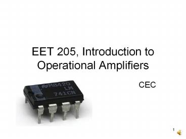
EET 205, Introduction to Operational Amplifiers
- CEC
2
Contents
- Ideal OPAMP.
- OPAMP Parameters.
- OPAMP Configurations.
- IC 741.
- Power Supply Connections.
- Reference Books.
3
OPAMP Introduction
- Two input terminals, one output terminal, two
power supply terminals. - Amplifies the input difference.
4
OPAMP Introduction
5
Ideal OPAMP
6
Ideal OPAMP
- Infinite Input Impedance draws no current at
the input terminals. - Infinite Gain - Small differential input voltages
amplified. - Output Voltage independent of current drawn from
the output - can drive infinite number of
devices. - Zero Output Impedance for impedance matching.
- Not practical to realize.
7
IC Packages
- Metal Can Package (TO).
- Dual in-line package.
- Flat package or flat pack.
- May contain one, two or four OPAMPS.
8
IC Packages
9
IC Packages
10
Power Supply Connections
Common Ground
5 V to 22 V
11
Power Supply Connections
12
OPAMP Characteristics
13
OPAMP Saturation
14
Open Loop Configuration
- No feedback from output to input.
- May saturate even for low magnitude inputs.
- Inverting and Noninverting Configurations.
- Limited Number of Applications Zero Crossing
Detector, Comparator etc.
15
Open Loop Configuration
Inverting Zero Crossing Detector
16
Open Loop Configuration
Noninverting Zero Crossing Detector
17
Open Loop Configuration
Inverting Level Comparator
18
Open Loop Configuration
Noninverting Level Comparator
19
Open Loop Configuration
Noninverting
Inverting
Comparator
20
Closed Loop Configuration
- Negative feedback for amplifiers.
- Feedback using external components.
- (eg feedback resistor)
- OPAMP utility increased.
- Inverting and non-inverting configuration.
- Not likely to saturate.
- As amplifiers, oscillators etc.
21
Closed Loop Configuration
Negative Feedback
22
Voltage Follower
Unity Gain
23
Schmitt Trigger
Closed Loop
Exhibits Hysteresis Action
Inverting
Noninverting
Positive Feedback
24
Common Mode Rejection Ratio
25
Slew Rate
Rate of Change of Output Voltage
26
Slew Rate
27
Slew Rate
28
Linear IC Manufacturers
29
IC 741 Versions
30
IC 741 Pin Configuration
31
Ideal OPAMP vs IC 741
32
IC 741 Maximum Ratings
33
References
34
References
35
Thank You


