
John Deere PowerTech 10.5L and 12.5L Diesel Engines Level 6 Electronic Fuel Systems With Lucas EUIs Service Repair Manual Instant Download (CTM188) - PowerPoint PPT Presentation
Title:
John Deere PowerTech 10.5L and 12.5L Diesel Engines Level 6 Electronic Fuel Systems With Lucas EUIs Service Repair Manual Instant Download (CTM188)
Description:
John Deere PowerTech 10.5L and 12.5L Diesel Engines Level 6 Electronic Fuel Systems With Lucas EUIs Service Repair Manual Instant Download (CTM188) – PowerPoint PPT presentation
Number of Views:0
Title: John Deere PowerTech 10.5L and 12.5L Diesel Engines Level 6 Electronic Fuel Systems With Lucas EUIs Service Repair Manual Instant Download (CTM188)
1
CTM188 - PowerTech 10.5 L and 12.5 L Diesel
Engines Level 6 Electronic Fuel Systems With
Lucas EUIs Remove and Install High Pressure
Regulating Valve
Remove and Install High Pressure Regulating Valve
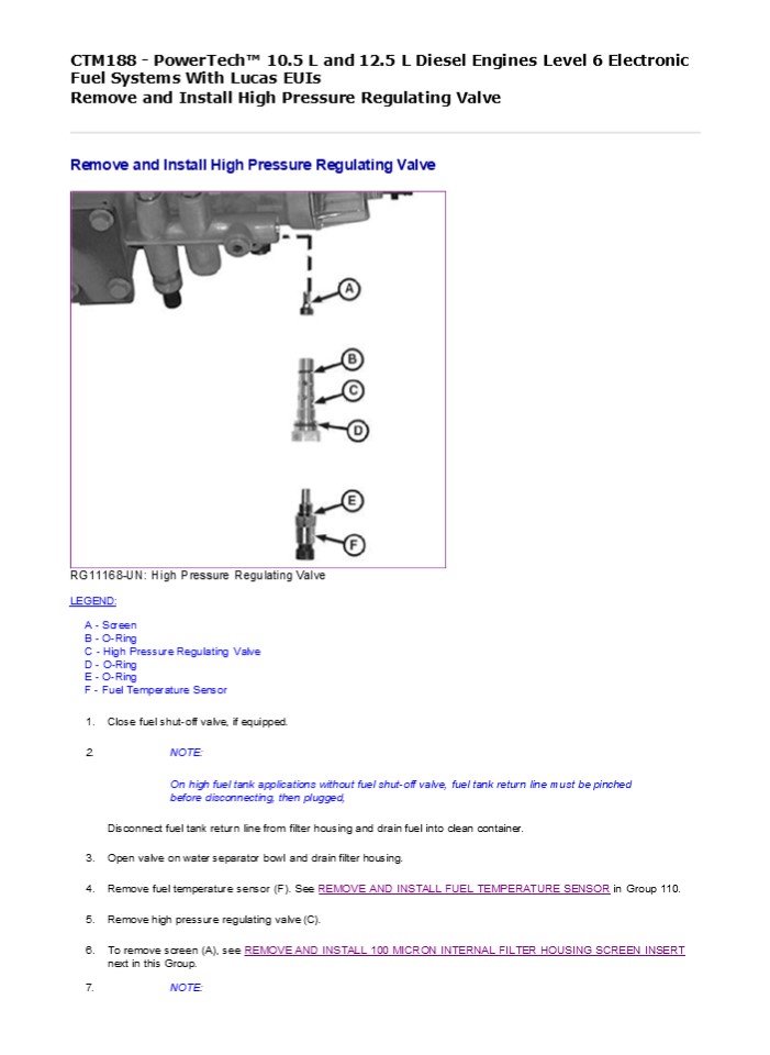
- RG11168-UN High Pressure Regulating Valve
- LEGEND
- A - Screen
- B - O-Ring
- C - High Pressure Regulating Valve
- D - O-Ring
- E - O-Ring
- F - Fuel Temperature Sensor
- Close fuel shut-off valve, if equipped.
- NOTE
- On high fuel tank applications without fuel
shut-off valve, fuel tank return line must be
pinched before disconnecting, then plugged, - Disconnect fuel tank return line from filter
housing and drain fuel into clean container. - Open valve on water separator bowl and drain
filter housing.
7.
NOTE
2
High pressure regulating valve is not repairable.
Do not disassemble valve. If defective, replace
entire assembly. Clean and inspect all parts.
Replace all O-rings. 8. Install parts in
reverse order. If removed, install screen (A).
See REMOVE AND INSTALL 100 MICRON INTERNAL FILTER
HOUSING SCREEN INSERT next in this
Group. Tighten regulating valve to
specifications.
Item
Measurement
Specification
High Pressure Regulating Valve-to- Filter Housing
Torque
14 Nm (124 lb-in.)
- Install fuel temperature sensor (F). See REMOVE
AND INSTALL FUEL TEMPERATURE SENSOR in Group 110. - Add fuel to filter housing between minimum and
maximum marks on housing. Fuel can be added by
throttling the fuel shut-off valve (if equipped),
or by removing cover and adding fuel from a clean
container.
DPSG,OUO1004,1014-19-20150709
3
CTM188 - PowerTech 10.5 L and 12.5 L Diesel
Engines Level 6 Electronic Fuel Systems With
Lucas EUIs Remove and Install 100 Micron Internal
Filter Housing Screen Insert
Remove and Install 100 Micron Internal Filter
Housing Screen Insert
RG11168-UN High Pressure Regulating Valve
RG10358-UN Remove Screen LEGEND A - 100 Micron
Screen B - O-Ring C - High Pressure Regulating
Valve D - O-Ring E - O-Ring F - Fuel Temperature
Sensor K - Allen Wrench with Rubber Band 1.
Remove fuel temperature sensor (F). See REMOVE
AND INSTALL FUEL TEMPERATURE SENSOR in Group 110.
4
https//www.ebooklibonline.com Hello dear
friend! Thank you very much for reading. Enter
the link into your browser. The full manual is
available for immediate download. https//www.ebo
oklibonline.com
5
Remove high pressure regulating valve (C). See
REMOVE AND INSTALL HIGH PRESSURE REGULATING VALVE
earlier in this Group.
2.
IMPORTANT
- If allen wrench is pushed too far into 10 micron
screen during removal and installation, screen
may be damaged. Tie a rubber band (K)
approximately 10 mm (3/8 in.) from end of allen
wrench, as shown, to prevent screen damage. - NOTE
- Screen is approximately 91 mm (3-5/8 in.) up in
bore of filter housing. Use a long allen wrench. - Attach a rubber band (K) on end of 5 mm allen
wrench and remove 10 micron screen (A) from
filter housing. - Clean and inspect screen.
- Using allen wrench with rubber band, install
screen in filter housing and tighten to the
following specification.
Item 100 Micron Internal Filter Housing Screen
Measurement Torque
Specification 5 Nm (44 lb-in.)
5. Install pressure regulating valve parts
(BD). See REMOVE AND INSTALL HIGH PRESSURE
REGULATING VALVE earlier in this Group. Install
fuel temperature sensor parts (E) and (F). See
REMOVE AND INSTALL FUEL TEMPERATURE SENSOR in
Group 110.
DPSG,OUO1004,1030-19-20061219
6
CTM188 - PowerTech 10.5 L and 12.5 L Diesel
Engines Level 6 Electronic Fuel Systems With
Lucas EUIs Remove and Install Fuel Filter Check
Valve
Remove and Install Fuel Filter Check Valve
- RG10307-UN Fuel Filter Check Valve
- LEGEND
- A - O-Ring
- B - Check Valve
- C - O-Ring
- Close fuel shut-off valve (if equipped).
- Disconnect fuel line (shown disconnected) and
remove check valve (B). Remove O-rings (A) and
(C) from both ends of check valve. - Install check valve in filter housing and tighten
to specifications.
Item
Measurement
Specification
Fuel Filter Check Valve to Fuel Filter Housing
Torque
33 Nm (24 lb-ft)
4. Connect fuel line and tighten to
specifications.
Item Measurement Fuel Line-to-Fuel Filter Check
Valve Torque
Specification
24 Nm (18 lb-ft)
5. Open fuel shut-off valve.
DPSG,OUO1004,1016-19-20150709
7
CTM188 - PowerTech 10.5 L and 12.5 L Diesel
Engines Level 6 Electronic Fuel Systems With
Lucas EUIs Remove and Install Primer Pump
Remove and Install Primer Pump
- RG10360-UN Primer Pump
- LEGEND
- A - Primer Pump
- B - Adapter
- Remove primer pump (A).
- If required, remove adapter (B).
- Clean and inspect parts.
- Install primer pump and adapter with new O-rings
and tighten to specifications.
Item
Measurement
Specification
Fuel Primer (Single Rail Fuel System)
Torque
14 Nm (124 lb-in.)
Fuel Primer-to-Fuel Filter Housing Adapter
(Single Rail Fuel System)
Torque
11 Nm (97 lb-in.)
DPSG,OUO1004,1032-19-20061219
8
CTM188 - PowerTech 10.5 L and 12.5 L Diesel
Engines Level 6 Electronic Fuel Systems With
Lucas EUIs Remove and Install Single Rail Fuel
Supply Pump
Remove and Install Single Rail Fuel Supply Pump
RG10289-UN Fuel Supply Pump
RG10288-UN Removing Fuel Supply Pump LEGEND A -
Supply Pump Outlet Line B - Fitting C - Fuel
Supply Pump D - Supply Pump Inlet Line E -
Fitting F - Mounting Bracket IMPORTANT
9
- Plug or cap all fuel system connections and
passages as lines or components are removed to
keep debris out using JDG998 Fuel System Cap Plug
Kit. - Remove Fuel Supply Pump
- NOTE
- Fuel flow through cylinder head may vary by
engine application. Supply pump (A) may be
mounted as shown with fuel entering the front
left side of the cylinder head and exiting the
back of the head. On some machine applications,
the fuel supply pump is rotated 180 and the fuel
lines on cylinder head are reversed, with fuel
entering the back of the head and exiting the
front left side of the head. - Add a reference mark (supply pump-to-cylinder
head) and label fuel lines as they are
disconnected, to ensure correct reinstallation of
supply pump. - Remove two fuel lines (A) and (D) connected to
fuel supply pump. Cap all lines and fittings to
keep debris out of fuel system. - Remove four cap screws securing supply pump to
mounting bracket (F) and remove pump. Remove and
discard O- ring.
3.
NOTE
- Fuel supply pump is not serviceable replace pump
if determined to be defective. - Remove fittings (B) and (E) from pump and clean
thoroughly if pump is to be replaced. - Install Fuel Supply Pump
- Inspect the fuel supply pump drive pin. If the
pin is worn or is able to be rotated, replace the
drive pin. See Replace Fuel Supply Pump Drive Pin
in Section 02, Group 50 of CTM100. - Install fittings onto new pump using new O-rings.
Tighten fittings securely. - Ensure that drive coupler set screw is tightened
to specifications on supply pump drive shaft with
end of shaft flush with coupler ID. Check drive
coupler on camshaft drive pin also adjust as
needed.
Item
Measurement
Specification
Fuel Supply Pump and Camshaft Drive Coupler Set
Screws
Torque
4 Nm (3 lb-ft)
- Position new rubber spider (vibration absorber)
on drive coupler. Position new O-ring on face of
supply pump. - If removed, apply AR54749 Soap Lubricant to new
O-ring on supply pump mounting bracket (F) and
install. Tighten mounting bracket cap screws to
specifications.
Item
Measurement
Specification
Fuel Supply Pump Mounting Bracket Cap Screws
Torque
50 Nm (37 lb-ft)
- Install fuel supply pump with rubber spider
properly meshed with coupler on rear of camshaft. - Install four cap screws and tighten to
specifications.
Item Measurement Specification
Fuel Supply Pump-to-Bracket Torque 25 Nm (18 lb-ft)
8.
IMPORTANT
10
Before connecting ORFS fuel line fittings, be
sure O-ring is correctly positioned in the groove
of fitting. Tighten fitting ONLY to specified
torque. DO NOT OVERTIGHTEN. Install two fuel
lines and tighten to specifications.
Item Measurement Specification
Fuel Line ORFS Fittings Torque 24 Nm (18 lb-ft)
DPSG,OUO1004,1000-19-20150420
11
CTM188 - PowerTech 10.5 L and 12.5 L Diesel
Engines Level 6 Electronic Fuel Systems With
Lucas EUIs Remove and Install Electronic Unit
Injectors (Single Rail Fuel System)
Remove and Install Electronic Unit Injectors
(Single Rail Fuel System)
- RG8279-UN Unit Injector Clamp Screws
- LEGEND
- A - Clamp Cap Screws
- IMPORTANT
- Electronic unit injectors on dual rail fuel
systems are different than injectors on single
rail systems. Use the appropriate injector for
engine/fuel system applications. Additionally,
early single rail fuel systems for engines - S.N. ( 29999) use different injectors than later
single rail systems for engines S.N. (30000 ).
Replace injector with the same type removed. DO
NOT intermix injectors. See parts catalog for
correct applications. - IMPORTANT
- Whenever EUI is replaced, sleeve in cylinder head
must be replaced also. See Replace Unit Injector
Sleeve in Cylinder Head Using JDG981 is Section
02 Group 020 of Base Engine manual. - Remove rocker arm cover. See REMOVE AND INSTALL
ROCKER ARM COVER in CTM100, Section 02, Group
020. - Remove rocker arm shaft assembly. See REMOVE
ROCKER ARM ASSEMBLY in CTM100, Section 02, Group
020. - Disconnect fuel lines and drain fuel from lines
and fuel rail in cylinder head.
- Reconnect lines (or install cap plugs from JDG998
Fuel System Cap Plug Kit) to keep debris out of
fuel system. - Remove injector hold-down clamp cap screws (A).
12
6. RG8280-UN Position Prybar
- RG8281-UN Removing Unit Injector
- LEGEND
- A - Hold-Down Clamp
- B - Prybar
- Pry upward on the injector hold-down clamp (A)
against cylinder head using a prybar (B) as
shown. - Remove injector and clamp from cylinder head.
Label injector for installation in same cylinder
location as removed. - Immediately plug injector bore with clean cap
plug to keep debris out of fuel system. - Remove injector O-rings and discard.
- Store injector in a clean, lint-free container.
- Install Electronic Unit Injectors
- NOTE
13
3.
IMPORTANT
Press on top of injector plunger with palm of
hand to properly seat O-rings and center injector
between valve springs. NOTE New EUI hold-down
clamp cap screws have pre-applied sealant.
RG10249-UN Injector Hold-Down Clamp Screws
RG9574-UN Torque-Turn EUI LEGEND A - Clamp Cap
Screw B - Ratchet Handle Install unit injector
with hold-down clamp into same cylinder as
removed (solenoid outward toward exhaust manifold
side of engine at equal distance between exhaust
valve springs). Apply LOCTITE 242 Thread Lock
and Sealer to used hold-down cap screw. Initially
tighten cap screw to specifications.
Item
Measurement
Specification
Electronic Unit Injector Hold-Down Clamp Cap
Screws
Initial Torque
20 Nm (177 lb-in.)
- Mark head of cap screw (A) at twelve o'clock
position (viewed from rear) using a paint stick. - Install 13 mm swivel socket on head of cap screw.
Position ratchet handle (B) parallel with
centerline of engine camshaft/crankshaft. - Torque-turn cap screw to the following
specification.
14
Item
Measurement
Specification
Electronic Unit Injector Hold-Down Clamp Cap
Screws
Torque-Turn
90 Additional Rotation
6. Remove socket from head of cap screw and
verify that mark has been tightened/turned 90
from its original position.
7.
IMPORTANT
DO NOT use red or blue LOCTITE on solenoid
studs. Bonding strength is too high for small
studs, making future removal impossible without
twisting off stud.
RG10294-UN Wiring Terminal Nuts LEGEND A -
Retaining Nuts Reconnect injector solenoid
wiring leads onto solenoid studs. Apply LOCTITE
222 Small Screw Thread Locker (PM38653) to studs
and tighten retaining nuts (A) to specifications.
Item
Measurement
Specification
Electronic Unit Injector Wiring Harness Connector
Nuts
Torque
2 Nm (18 lb-in.)
- Install valve bridges, push tubes, and rocker arm
assembly. Adjust valve stem-to-bridge clearances.
See INSTALL ROCKER ARM ASSEMBLY in CTM100,
Section 02, Group 020. - If removed or loosened, tighten all harness and
line clamps to specifications.
Item
Measurement
Specification
Fuel Line Clamps
Torque
5 Nm (44 lb-in.)
Electronic Unit Injector Harness-to- Shaft Clamps
Torque
35 Nm (26 lb-ft)
Electronic Unit Injector Wiring Connector
Bracket-to-Rear of Head
Torque
25 Nm (18 lb-ft)
10. Adjust electronic unit injector preload as
detailed later in this Group.
LOCTITE is a registered trademark of Loctite Corp.
VP98307,000010A-19-20150324
15
CTM188 - PowerTech 10.5 L and 12.5 L Diesel
Engines Level 6 Electronic Fuel Systems With
Lucas EUIs Adjust Electronic Unit Injector Preload
Adjust Electronic Unit Injector Preload
RG8228A-UN JDG971 Timing Pin in Camshaft
RG8227D-UN JDG971 Timing Pin in Crankshaft
16
RG11165-UN Camshaft Timing Slot LEGEND A -
JDG971 Timing Pin B - JDG820 Flywheel Turning
Tool C - JDG971 Timing Pin D - Single Timing
Slot E - Double Timing Slot 1. Remove plug from
cylinder block and install JDG820 Flywheel
Turning Tool (B).
2.
IMPORTANT
Timing pin MUST BE installed in slot of camshaft
first. Then install second timing pin in
crankshaft slot by carefully rocking flywheel
back and forth. Rotate engine flywheel in
running direction (counterclockwise as viewed
from rear) until JDG971 Timing Pin (A) engages
single timing slot (D) in camshaft. The proper
timing slot can be found by viewing camshaft
timing lobe through camshaft timing pin bore
while rotating engine. The double timing slot (E)
will be at approximately 11 o'clock (viewed from
rear of engine) when pin is installed in slot
(D). This ensures that engine is locked at TDC of
No. 1 cylinder's compression stroke. Intake and
exhaust rocker arms on No. 1 cylinder should be
loose. 3. Remove threaded plug from crankshaft
timing hole below oil cooler and filter housing
assembly.
4.
IMPORTANT
DO NOT insert timing pin full depth into cylinder
block crankshaft timing hole when rotating
engine flywheel until double slot on camshaft
timing lobe is at approximately 11 o'clock
(viewed from rear of engine) to avoid crankshaft
counterweight bending timing pin. Slightly move
engine flywheel back and forth with turning tool
until a second JDG971 Timing Pin (C) can be
installed in slot in crankshaft. This ensures
that camshaft and crankshaft are in sync
(properly timed). If timing pin does not enter
crankshaft timing slot, crankshaft is not
properly timed with camshaft. Crankshaft MUST BE
timed to camshaft. See Check And Adjust
Camshaft-To-Crankshaft Timing in the Base Engine
manual.
17
Suggest If the above button click is invalid.
Please download this document first, and then
click the above link to download the complete
manual. Thank you so much for reading
18
- 5.
- RG8270-UN Unit Injector Adjusting Screw
- LEGEND
- A - Lock Nut
- B - Adjusting Screws
- Loosen lock nut (A) and loosen cylinders Nos. 3,
5, and 6 injector rocker arm adjusting screws (B)
to relieve tension. - Slowly tighten adjusting screw until rocker arm
roller contacts camshaft lobe at 0.0 clearance. - Tighten adjusting screw an additional 1/2 turn
(180) to preload injector. Tighten adjusting
screw lock nut to specifications while holding
adjusting screw stationary.
Item
Measurement
Specification
Electronic Unit Injector Adjusting Screw Lock Nut
Torque
65 Nm (48 lb-ft)
- Remove both timing lock pins, rotate crankshaft
one full revolution (360) and pin crankshaft
only. Engine will now be locked at No. 6 TDC. - Set injector preload on cylinders Nos. 1, 2, and
4. - Install plug in timing pin hole in block and
tighten to specifications.
Item Measurement Specification
Timing Pin Plug in Cylinder Block Torque 33 Nm (24 lb-ft)
RG,RG34710,263CONV-19-20150709
19
https//www.ebooklibonline.com Hello dear
friend! Thank you very much for reading. Enter
the link into your browser. The full manual is
available for immediate download. https//www.ebo
oklibonline.com
Recommended
CrystalGraphics Presentations


