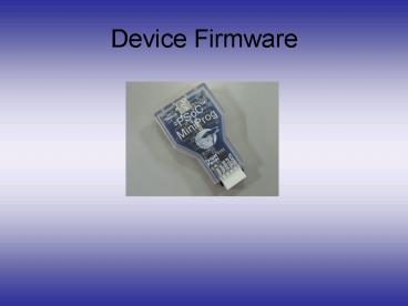
Device Firmware PowerPoint PPT Presentation
Title: Device Firmware
1
Device Firmware
2
PSOC Components
- The M8C core contains
- An 8-bit processor with flash memory
- Analog blocks that contain the Analog to digital
converter - Digital blocks to implement any additional logic
needed - Additional relevant components on board includes
- 4 LEDs
- 2 Potentiometers
- 2 Push buttons
- LCD Display
3
Design Components
- The steps necessary in implementing the design
include - Using the Device Editor in the PSOC designer to
setup the hardware. - Using jumper wires to connect components such as
LEDs, Push buttons and the Potentiometer. - Writing code in C and or assembly to control the
hardware itself as well as to coordinate
communications with the controlling computer.
4
Setting Up Hardware in the PSOC Designer
5
Setting Up Hardware in the PSOC Designer
- Hardware setup is done using the Device Editor
tool in the PSOC Designer. - This involves
- Specifying what modules to include in the user
module selection view. - Connecting the components, blocks and buses in
the interconnect view - Specifying port properties. Eg names of pins, the
type of connection, whether driven hi or low.
6
Writing Firmware in the PSOC Designer
- Generate Application tool in the Device Editor
creates some of the libraries necessary to
control certain hardware components, eg the LCD
display ADC. - It maybe necessary to write additional code in
assembly to control components like LEDs and
reading push buttons. Tasks like debouncing the
button is taken care of in these codes. - - All the above functions are called from a main
function, which also coordinates data acquisition
and storage and communications with the computer.
7
Modifications Made to Existing Examples
- Some of the port set-ups in the hardware editor
had to be modified. - This also required modification of register
addresses in the assembly code as well as some of
the code itself. - Much modifications were necessary in the main
function and additional called functions to
enable desired functionality as well as USB
communications.
PowerShow.com is a leading presentation sharing website. It has millions of presentations already uploaded and available with 1,000s more being uploaded by its users every day. Whatever your area of interest, here you’ll be able to find and view presentations you’ll love and possibly download. And, best of all, it is completely free and easy to use.
You might even have a presentation you’d like to share with others. If so, just upload it to PowerShow.com. We’ll convert it to an HTML5 slideshow that includes all the media types you’ve already added: audio, video, music, pictures, animations and transition effects. Then you can share it with your target audience as well as PowerShow.com’s millions of monthly visitors. And, again, it’s all free.
About the Developers
PowerShow.com is brought to you by CrystalGraphics, the award-winning developer and market-leading publisher of rich-media enhancement products for presentations. Our product offerings include millions of PowerPoint templates, diagrams, animated 3D characters and more.

