Tanner Tools I' - PowerPoint PPT Presentation
1 / 23
Title:
Tanner Tools I'
Description:
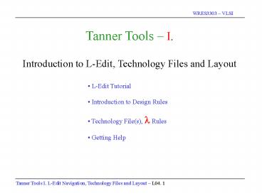
Tanner Tools I. Introduction to L-Edit, Technology Files and Layout. L-Edit Tutorial ... Tanner Tools I. L-Edit Navigation, Technology Files and Layout L04. 3 ... – PowerPoint PPT presentation
Number of Views:874
Avg rating:3.0/5.0
Title: Tanner Tools I'
1
Tanner Tools I. Introduction to L-Edit,
Technology Files and Layout
- L-Edit Tutorial
- Introduction to Design Rules
- Technology File(s), ? Rules
- Getting Help
2
Circuit Design
Layout
Layering and Fabrication
3
- L-EDIT Full Custom All-Angle Layout Editor
- Technology Configurable
- Fully Hierarchical
- Design Navigator
- Customizable Keyboard, Palette, Rulers
- Command Line Interface
- MDI- Layout Text
- GDSII, CIF, DXF support
- User Properties on objects
- Cross-section Viewer
- DRC
4
- Concepts
- software icons
- opening L-Edit
Start Windows Open L-Edit Pro
5
- Concepts
- initial window
- creating a new tdb
- selecting a technology file
File gt New gt Browse gt mami150.tdb (mosis ami 1.5u)
6
Technology Setup
- Concepts
- technology files
- default settings
- ?
- Technology setups are settings whichare stored
in the design file, and commonlyshared with
other design files, including - Technology name
- Units and Grids
- internal unit ?? ? micron ? locator unit
- Default settings
- External libraries
- Layers Palette
- Design Rules
7
- Concepts
- zooming control
- hierarchical view window
- cell naming convention
- window layout and menu items
- cursor control and item selection
All Levels
Hierarchical View
Mouse Coordinates - inmicrons relative to
homeposition of display.
Zoom - and - keysor click on magnifier and
use left mouse to draw a box around area to
expand.
Home
Open Hierarchical View Expand Layout Window
Find Home
8
(No Transcript)
9
Add N implant location using Active layer
(8x17)
- Concepts
- adding layers
- active can be either P or N, how does L-Edit
know?
10
- Concepts
- design rule check DRC
- specifying a region or selecting the entire
cell - specifying the test size
Tools gt DRC (design rule check) on a regular
basis. Click OK.
11
Note DRC errors. Both an error message as well
as the error (1.000 lt 2 Lambda) are shown.
- Concepts
- identifying errors graphically
- identifying errors by text message
- fixing errors
- can be overwhelming
12
- Concepts
- fixing DRC errors
- adding poly gates, where is the insulation?
- how large should the poly be?
Fix the error (the active region must be at least
2? from the cell edge). Add an active region
for the P-Select.
Add polysilicon gate
13
- Concepts
- how to create a set of basic cells and then
use them in various designs - creating a new cell
- renaming a cell
- copying a cell
Create a new layout. Add cell0 to the cell1.
14
- Concepts
- grouping designs
- copying designs
note box around the imported cell
Note that the new cell is grouped and cannot
be separated. Ungrouping a cell design (if you
want to) makes the underling design accessible.
15
- Concepts
- ungrouping a cell
Once you ungroup the cell, you will be able to
move individual cell components.
16
- Concepts
- adding metal1 layers
- biasing substrate
- may not be wrong from a DRC viewpoint, but
may be hard to decipher from a graphical
viewpoint
Add Metal1 layers. Note in this design that
the Metal1 overlaps the poly on one side and is
2? from the Poly on the other side. DRC.
Fix the design.
17
- Concepts
- add active connections
- use correct layer/tool
- DRC
Add Active Contacts.
18
- Concepts
- add poly contact
- use correct layers and tools
- note color changes
Add an area of Poly that can be used for a
Metal1 connection. Then, add Metal1 and a
Poly-Metal1 connector.
19
- Concepts
- continue to DRC the design as you develop it
DRC !
20
Final NMOS design with the addition of metal2 and
via contacts.
21
Final PMOS design with the N-Well defined for
proper P-Select doping.
22
Getting Help in L-Edit Its all on-line!
23
- Whats Next?
- How to examine the cross-sectional view of a
design. - How to extract a netlist file of a design.
- How to add the library files and a test bench to
- your extracted netlist file.
- How to run T-Spice on the modified netlist file.
- How to view the results from Spice using W-Edit.


