Open Systems Interconnect OSI Model - PowerPoint PPT Presentation
1 / 11
Title:
Open Systems Interconnect OSI Model
Description:
Automatic Collision Detection. Transmitter A. Dominant (0) Recessive (1) Transmitter B ... (0) from B, A knows collision occurred and stops transmitting (will retry ... – PowerPoint PPT presentation
Number of Views:81
Avg rating:3.0/5.0
Title: Open Systems Interconnect OSI Model
1
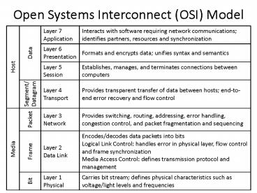
Open Systems Interconnect (OSI) Model
2
Controller Area Network Standard
- Defines Physical Layer (L1)
- Defines Data Link Layer (L2)
- Defines how to Transport (L4) small (8 bytes)
datagrams - No flow control (L3 and L4)
- No sequencing and fragmentation (L3)
- No Session (L5) or Presentation (L6) specs
- Different Higher Layer Protocols (HLPs) handle
the rest
3
Common CAN HLPs
- CanKingdom
- CANopen
- CCP/XCP
- DeviceNet
- SAE J1939
- OSEK
- SDS
- These define the Object Layer (layers not
defined by the CAN standard)
4
CAN Physical Layer Voltages
- Open collector (wired-OR) NRZ
- Dominant bits are logical 0
- Recessive bits are logical 1
- Provides arbitration free transmission
If A transmits recessive (1) and sees dominant
(0) from B, A knows collision occurred and stops
transmitting (will retry 6 clock cycles after end
of dominant message)
5
CAN Physical Layer Timing
- Each node has its own clock
- Synchronization done by dividing bit time into
four segments
Bit Time
Sync
Propagation
Phase Segment 1
Phase Segment 2
Clock
- Phases 1 2 adjusted based on network and node
conditions - Sample between Phase 1 2
6
CAN Data Link Layer
- Specifies four message types
- Data contains data for transmission
- Data Request (Remote) requests transmission of a
specific identifier - Error transmitted by any node detecting an error
- Overload injects a delay between data and/or
remote frames
7
CAN Data Frames
For Data Request RTR 1 (recessive) and DLC 0
(data field empty)
8
Error Frames
- Active error generated by transmitter
- Passive error generated by receiver
- Error Types
- Bit Send recessive, read dominant
- Stuff more than 5 consecutive bits of same
polarity - CRC computed and received CRCs not equal
- Form invalid bits in field
- ACK no acknowledgement from receiver
9
Overload Frames
- Two overload conditions
- Internal conditions of receiver it cant keep
up - Dominant bit detected during expected
intermission (interframe space)
10
Byte Data Link Controller (BDLC)
- Physical Layer has three forms
- 2-wire 10.4 Kbps, UART, NRZ (Chrysler)
- 2-wire 41.6 Kbps pulse width modulated (Ford)
- 1-wire 10.4 Kbps variable pulse width (GM)
- High level 4.25-20 V Low level lt 3.5 V
- Buses use weak pull-down, driver pulls it high
- High signals are dominant
- High and low values are bit symbols with specific
times
11
BDLC Data Link Layer
3 byte headers contain destination and source
addresses


