
Ferry Fuel System PowerPoint PPT Presentation
1 / 23
Title: Ferry Fuel System
1
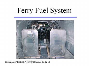
Ferry Fuel System
Reference Pilot Intl PI-1200M Manual dtd 12-98
2
Outline
- Components
- Normal Operation
- Emergency Operation
- Limitations/Restrictions
3
Components
- 2 Aluminum Tanks
- 2 Tank Drain Lines
- Electric/Manual Pump
- 2 Sets (4 total) Fuel Selector Assemblies
- 2 ferry tank selectors
- 2 aircraft fuel tank selectors
- Surge Tank
- Vent Line
4
Tanks
- 120 Gallon Capacity
- Three Baffles Inside To Reduce Sloshing
- Serviced Through Open Port Cap
- Mounted on Wooden Shoring
- Drain Line Off T Fitting on Aft Of Tank
5
Pump
- Electric Rotary Action (may have one or two
electric pumps) - Manual Wobble Action
- Site Glass on Aft Line
- Capability of 90 GPM transfer rate
6
Fuel Selector Assemblies
- One set (ferry tank selector) prior to pump
- One set (aircraft fuel tank selector) plumbed aft
of pump - Manually operated by crew
7
Selector Valve Operation
Valves Closed
Valves Open
8
Ferry System Schematic
To Aircraft Fuel System
Aircraft Fuel Tank Selector Valves
Pump
Ferry Tank Selector Valves
Fuel Tank
Drain Line
9
Aircraft Fuel System Interface
10
Vent System
- Vent Lines Run From Top Of Fuel Tanks Near Filler
Caps... - To surge tank
11
Surge Tank
- Mounted aft of tanks
- Equalizes pressure between the ferry tanks and
the cabin - Contains 2 one-way check valves.
IN one-way check valve equalizes pressure
between the tanks and the cabin during
pressurized operation. OUT one-way check valve
equalizes pressure between the tanks and cabin in
the event of cabin depressurization.
12
Vent System (Continued)
- Through Surge Tank to Aft Vent Probe Assembly
- Vent Probe Faces Forward
- Has Two Drilled Anti-Ice Holes
13
Vent System Schematic
Vent Probe
Fuel Tank
Fuselage
Surge Tank
14
Normal Operation
Prior to Flight
- Fill the system to desired level (not more than 1
to 1½ inches from top). - Place aft end of drain lines outside cabin door
and drain about 1 pint from each line into sample
bottle (removes moisture). - Test ferry system on ground to purge it of air.
15
Normal Operation
In the Air
- Take off and climb using normal fuel.
- Use fuel until mains are about ½ full.
- Open the desired ferry fuel tank selector
(recommend both). - Open either or both aircraft fuel tank selectors
(can be used to equalize levels). - Turn on either or both ferry fuel pumps.
16
Normal Operation
In the Air (continued)
- Observe the quantity of fuel in the main fuel
tanks - discontinue when they near full to
prevent venting overboard. - Observe the fuel flow sight gauge on the ferry
pump - when air bubbles appear/increase close the
ferry tank selectors, turn off transfer pumps,
and close the aircraft fuel tank selectors.
17
Emergency Operation
NOTE If the aircraft electrical system fails
and/or the electric fuel pump(s) become
inoperative, fuel can be transferred using the
manually operated wobble pump.
- Operate the manual wobble pump by moving handle
back and forth about one complete stroke per
second. - Observe fuel quantities as per normal operation
procedures.
18
Emergency Operation
CAUTION If the aircraft is pressurized and ferry
fuel transfer is attempted by any means, fuel is
going to transfer rapidly when any aircraft fuel
tank selector valve is open because of the cabin
pressure differential, without operating either
the electric fuel pumps or the manual wobble
pump. The IN one-way check valve in the surge
tank equalizes the cabin pressure and the air
pressure over the fuel in the ferry fuel tanks.
Opening the selector valves opens a path for the
fuel to the main aircraft fuel tanks, which have
only ambient pressure over the fuel. Cabin
pressure will then force the fuel out of the
ferry fuel tanks into the aircraft main fuel
tanks.
19
Limitations/Restrictions
- Cabin rate of descent must not exceed 1,500 FPM.
WARNING Failure to comply could result in the
collapse of the tanks. If the 1,500 FPM (cabin)
rate of descent is exceeded the air may not flow
through the surge tank and tank vent lines fast
enough to keep the tank air pressure and cabin
air pressure equalized. If an extreme emergency
dictates a greater rate of descent then loosening
or removal of the tank caps will allow the two
air pressures to equalize, but could allow fuel
fumes to escape into the cabin.
20
Limitations/Restrictions
- Maximum takeoff weight cannot exceed 16,200
pounds. - Vne must not exceed 216 KIAS.
- Vmo must not exceed 0.43 mach.
- Maximum fuel quantity in the ferry tanks cannot
exceed 240 U.S gallons total. - Aerobatics are prohibited.
21
Limitations/Restrictions
- Flight into known or forecast moderate or severe
turbulence is prohibited. - Occasional light turbulence is permissible.
- Ferry flights shall be conducted under VFR
conditions to the maximum extent possible. - Transfer fuel during level cruise flight only.
- Maximum landing weight 15,400 pounds.
22
Suggestions
- The ferry tanks do not have quantity gauges.
Monitor fuel truck gauge during servicing. - Completely empty both ferry tanks prior to final
destination. - Dont order the hamburger at Sonderstrom.
23
Questions?
Recommended
