Preparing TPC Installation - PowerPoint PPT Presentation
1 / 21
Title:
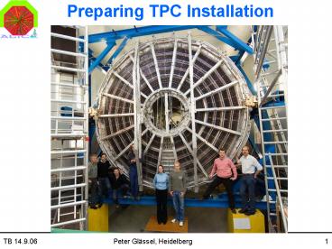
Preparing TPC Installation
Description:
Platform under shaft: intermediate support for Delphi Frame (DF) Before L3 magnet ... Lower into shaft onto intermediate support. Transfer to UX2 crane ... – PowerPoint PPT presentation
Number of Views:22
Avg rating:3.0/5.0
Title: Preparing TPC Installation
1
Preparing TPC Installation
2
Preparations in SXL2
- Remove clean room wall (towards Muon area) and
roof - Clear area for trailer
- Setup hydraulic station
DF TPC
DF TPC
3
Hydraulic station
- Alternative mobile crane
plan view
side view
4
Preparations in UX2
- Complete TPC/TRD heat screen
- Platform under shaft intermediate support for
Delphi Frame (DF) - Before L3 magnet
- Support for DF (surveyed)
- Space Frame area
- I-bars stored at BF
- Connection rails at BSF
- ITS platform (used when moving TPC)
5
(No Transcript)
6
Special precautions
- DF has 4 feet, but no deformation allowed
- Lifting jig is 3-point
- 4-point floating hydraulic support
- 3-point support (on trailer)
- TPC is a closed volume, safety bubbler with ?p lt
1 mbar - Watch ?p, ?T to avoid sucking air
- CO2 bottle on DF for replenishing
7
TPC transport
- Transport document is prepared
- DF TPC 24 t
- On SX2 crane from clean room to hydraulic station
- Raise to allow trailer to pass under DF
- Lower onto trailer
- Transport on trailer to SX2
- Pick-up with hydraulic station
- Lower to allow transfer to SX2 crane
- Lower into shaft onto intermediate support
- Transfer to UX2 crane
- Move to final support before L3 magnet
8
(No Transcript)
9
ITS platform
- Any number of segments possible
10
Installation sequence
- Based on previous experience in TPC-ITS
integration test - Align, install connection rails
- Move to IP under survey
- No adjustments of SF during moving foreseen,
expected deformations lt 2mm (cf. tolerance for
beam pipe 5 mm) - Align TPC at IP
- Move back to parking position under survey
- ITS installation
11
Spares
12
(No Transcript)
13
(No Transcript)
14
(No Transcript)
15
(No Transcript)
16
Alignment of TPC with Beam Axis
Once the TPC is in the final position, the TPC
axis is aligned with the beam axis. Again, only
the x,y,z, coordinates of the outer (and possibly
inner) reference rods on the shaft side can be
used to determine the position of the TPC.
17
Installation of 1st ITS rail section
Two 6m sections of the ITS rails are inserted
through the TPC and fixed by the ITS rail
fixation points on the frontabsorber. Then, the
fixations points are slightly opened to allow the
ITS rails to move to the parking position
together with the TPC. Since we assume that
after movement of TPC to parking position and
back to the IP the TPC ends up in the same
position, the above procedure will make sure that
the ITS rails are well aligned with the TPC when
it moves to the IP.
18
Heatscreen
19
(No Transcript)
20
(No Transcript)
21
(No Transcript)


