TransScan R PowerPoint PPT Presentation
1 / 26
Title: TransScan R
1
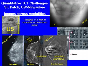
Quantitative TCT Challenges SK Patch, UW-Milwaukee
Images across modalities
Prototype TCT already competes w/conventional
scans!
EIT
TransScan RD
qualitative potentially quantitative
2
Mathematical Representation (assumes constant
soundspeed)
S upper hemisphere
inadmissable transducer
- Integrate f over spheres
- Centers of spheres on sphere
- Partial data only for mammography
S- lower hemisphere
3
FBP inversion (complete data)
- Backproject data (thanks to V. Palamodov!)
- Switch order of integration
- Use d-manifold identity (4x!) ?
- f ?Riesz potential ?
- f after high-pass filter
imaging object
Use co-area formula
4
Reconstruct Idealized Data - many different ways
- series solutions Norton, NortonLinzer
- - other measurement geometriesKunyansky06/07
- minimal filtering Xu05
- even space dims Finch07
- regularization schemes Schuster05/07,
Haltmeier05 - Neumann data FinchRakesh07
- injectivity proofs and range char. Finch06,
Ambartsoumian05/06 - iterative reconstruction Anastasio
!! apologies to other authors !!
5
TCT Wave Eq Model
mechanical
electrical
homog ICs
for I(t) ?(t)
6
Quantitative Imaging Challenges
- partial scan data - iterative recon
- transducer aperture size - integrating
detectors - acoustic attenuation - corr. for aphysical
model - variable soundspeed
- E field pattern/optical fluence corr.
- broadband data required, including low freqs
- unwanted EM coupling to US measurements
- transducer response - freq
dependent has limited sensitivity -
anisotropic
7
E-field pattern Acoustic Source
SOP to solve in frequency domain near carrier
frequency.
- 1) E is wave-like. At 100 MHz, ?air300cm,
?H20 33cm, ?fat70cm, ?muscle40cm - 2) tangential BCs force continuity of E x n
8
Rf coupling
Materials 434 MHz RF for 1?s pulse, 16kW peak
power 2.25? MHz Panametrics US transducer Phys
saline-filled straw lt 1mm diam
changed shape whenever big bags of salt water
walked into room
9
E-field in TCT Testbed
Very nearly TE103 Aluminum walls DI water not
lossy, waves resonate I(t) 1.
acoustic window
E-field on central plane inside
Power in
50kW amp yields instantaneous SAR gtgtgt
12W/kg
10
TCT Testbed - hardware
Translators - Sherry Yan, George Hanson, UWM-EE.
11
BCs - object orientation critical
21 aspect ratio
12
Imact on Rtct - qualitative
E in horizontal x-sections
13
Transducer Freq Response
- frequency content of measured pressures critical.
- Freq content is a function of true pressure, -
EM pulse, I(t) - transducer frequency
response, kA(?)
14
Transducer Freq Response
- Freq response filters image (Anastasio,et al)
- EM temporal profile also filters image
- Therefore, we characterize transducer frequency
response independently of EM frequency content,
using - hydrophone
- 2 transducers at same CF
15
Transd Freq Resp - measure
- Transmit w/transd A, receive w/hydrophone
- Transmit w/transd A, receive w/transd tct
TA Stiles (UW Madison) D Pachauri, N Purwar, P
Dey (UW-Milwaukee)
- far-field results
- broad- narrow-band pulses
16
Data -
hydrophone transducercalibration
measured
transducer sluggish
17
Frequency content response
Narrowband (NB)
18
Impulse Response
Broadband (BB) freq resp
complex, Herm symm
Narrowband (NB) freq resp
real symmetric
acausal
acausal
19
07 system - poor IOld RF pulse profile killed
frequency content
20
Conclusions
Transd char RF shielding both critical. RF
deposition clearly patient dependent will
require per/patient correction. (like
high-field MRI) Have much to learn - thanks to
those who have already given suggestions.
21
Backup slides
22
Transducer shield - Rev 1 by M Mitchell J
Becker
23
Rf shield - Rev 1 results
Nov 07
Jan - Mar 07
24
EM shield
25
Acoustic Attenuation Blurs
PNT Wells, Biomedical Ultrasonics
- where
- ?t are dual Fourier variables
- b1 in tissue b2 in fluids
- a0.1 MHz-1 cm-1
- L is distance in cm
- soundspeed c1540m/s
- EXP ill-posed physics
- Analytic correction by Anastasio/LaRiviere
26
Acausal Absorption Model
No atten

