TX radiation pattern PowerPoint PPT Presentation
1 / 9
Title: TX radiation pattern
1
TX radiation pattern
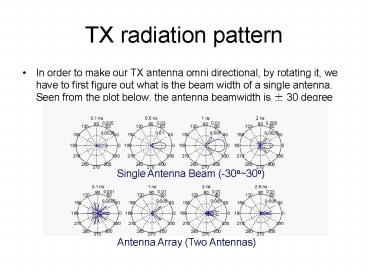
- In order to make our TX antenna omni directional,
by rotating it, we have to first figure out what
is the beam width of a single antenna. Seen from
the plot below, the antenna beamwidth is 30
degree
Single Antenna Beam (-30o30o)
- Single Antenna Beam (-3030)
- Antenna Array (Two Antennas)
2
TX radiation pattern
- We test two sets of radiation patterns, based
on rotating the TX 30-degree each (shown down)
and 20-degree each (shown right)
- 20-degree is more omni-directional compared to
30-degree, so during the channel measurement, we
will make the TX rotating 20 degree each step
3
Thermal noise cancellation Considerations
- Tolerable measurement time
- Equipment noise
- 2.5mV noise from oscilloscope
- Quantization noise Changes as signal peak goes up
- Input referred noise of amp
- Amplifier specification Gain, noise figure...
When the frequency of the pulse generator is
100kHz, even if we use average number equals
4096, the total time for a whole round
measurement will be 5.23hours, which is still
tolerable and can make our result more accurate.
- Other considerations
- High bandwidth
- Relative small number of bits for scope
- Jitter issue (keep within 10ps)
4
Input Referred Noise vs No. of Amplifiers
- When there are more than two amplifiers, the
noise is going to be dominated by the amplifiers
but not the oscilloscope, so our choice of two is
smart and lucky!
5
Different Estimations and Application
Nonparametric Methods
- Simplest periodogram
- Return power per unit frequency
- Good for high SNR and long data
- Not consist estimator
- Improved welch
- Dividing data into overlapping segments
- computing a modified periodogram of each segment
- averaging all the PSD estimates
- Can choose window and overlap percentage
- Variation and resolution trade off
- variance inversely proportional to the number of
segments - Good for low SNR
- Modern multitaper
- filtering signal through a filter bank optimal
FIR BP filters, derived from DPSS - Time-bandwidth parameter (NW) controls the
variation and resolution tradeoff - as NW increase, variation decrease and BW for
each taper increase - Pretty computing time-consuming
6
Different Estimations and Application Other
methods
- Parametric methods
- PSD is assumed to be the output of a linear
system driven by white noise - Yule-Walker autoregressive method
- Burg method and Covariance method
- Estimating the parameters (coefficients) of the
linear system which hypothetically "generates"
the signal - Better results than Nonparametric methods when
data is relatively short - Subspace methods (high resolution methods)
- High resolution and super resolution methods
- Self control signal number and threshold
- Multiple signal classification method and
Eigenvector method - Pseudo spectrum estimation
- Based on eigenanalysis of the autocorrelation
matrix - Effective detection for low SNR and spectra of
sinusoidal signals buried in noise
7
Interference deconvolution
- More exploration on the frequency deconvolution
- Add more consideration to the relative power
- Add more consideration to the harmonics of the
interference. - Capturing interference with the TEM horn
- For each case, deconvolution is performed by
considering
-- Measured scope and amplifier spectrum -- Final
deconvolved interference psd
-- Raw spectrum (interference convolve with the
scope and amplifier response)
8
Interference deconvolution
- Interference at Berkeley downtown (after
deconvolution) - Spectrum usage percentage
- Many frequency holes are presented, which can
potentially be used for the cognitive radio groups
- Especially low at 35GHz
9
(No Transcript)

