
Attrition - PowerPoint PPT Presentation
Title:
Attrition
Description:
Title: No Slide Title Author: Rick Fleeter Last modified by: fleeter Created Date: 2/27/2002 6:37:37 PM Document presentation format: On-screen Show – PowerPoint PPT presentation
Number of Views:85
Avg rating:3.0/5.0
Title: Attrition
1
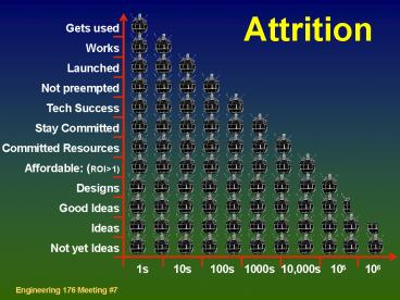
Attrition
Gets used Works Launched Not preempted Tech
Success Stay Committed Committed
Resources Affordable (ROIgt1) Designs Good
Ideas Ideas Not yet Ideas
1s 10s 100s 1000s 10,000s 105
106
2
The Lineup
- 7 - Radio Comms
- Radio Concepts
- Spectrum usage
- Link margin Orbits
- Modulation
- Antennas
- 8 - Thermal / Mechanical Design. FEA
- 9 - Reliability
- 10 - Digital Software
- 11 - Project Management Cost / Schedule
- 12 - Getting Designs Done
- 13 - Design Presentations
- 1 - Introduction
- 2 - Propulsion ?V
- 3 - Attitude Control instruments
- 4 - Orbits Orbit Determination
- 5 - Launch Vehicles
- 6 - Power Mechanisms
3
The New Lineup
- 7 - Radio Comms
- Radio Concepts
- Spectrum usage
- Link margin Orbits
- Modulation
- Antennas
- 10 - April 4 Thermal / Mechanical
Design. FEA - 8 / 9 - March 14 / 19 Reliability
- 9 - March 19 Digital Software
- 11 - Project Management Cost / Schedule
- 12 - Getting Designs Done
- 13 - Design Presentations
- 1 - Introduction
- 2 - Propulsion ?V
- 3 - Attitude Control instruments
- 4 - Orbits Orbit Determination
- 5 - Launch Vehicles
- 6 - Power Mechanisms
4
Design Roadmap
Or maybe Here
You Are Here
Define Mission
Concept
Solutions Tradeoffs
ConceptualDesign
Requirements
Analysis
Next week I want you to visit here
Top Level Design
PartsSpecs
Suppliers / Budgets
MaterialsFab
Iterate Subsystems
Final Performance Specs Cost
Detailed Design
5
Last week Power
6
And...Deployables
- Definitely not moving - for a long (or too long)
time - 1-g vs. 0-g ( vacuum) matters
- Tolerance v. launch loads
- Vacuum welds, lubricants, galling
- Creating friction - rigging
- Static strength, dynamics, resonance
- Safety inhibits (its physical)
Galileo didnt x 1
- Flaws, cracks, delamination, vibration
loosen/tighten - Minute population test experience (the Buick
antenna) - Total autonomy
- High current actuation
- Statistics - ways to work v. not
Freja did x 8
7
Due tonight
- Technical requirementsCreate a list of
technical requirements - even if it has TBDs in
it. ( revisit mission rqts)
- Preparation Radios Comms
- SMAD Chapter 13
- TLOM Chapters 7,8,9
- Tools selection
- Finite element
- Design and layout
- Presentation Graphics
- Systems designcreate a good looking cartoon
set of the spacecraft, orbit and ground segments
- Pick Something Physical
8
The plan for March 14(eve of ides)
- Part 1 (homework) Radio Strategy - what why
why not the other options Spacecraft Tx
Power, modulation, antenna selection, l same
for Ground Station Up and down link calcs
- Part 2 (class) System Design review /
discussion1 hour start on reliability 20
minute presentation x 3 groups 1 hour 2
reviewers (plus me) from AeroAstro - review, but
mainly help with designs and answer your
questions
9
Electromagnetic Spectrum Map
100 GHz 10 GHz 1 Ghz 100 MHz 10 MHz 1
MHz 100 KHz 10 KHz 1 KHz 100 Hz 10 Hz
- SHF and some radars 15 - 50 GHz - UHF /
L-band Television, spacecraft, cordless
cellular 500 MHz to 1 GHz - Short Wave radio
International broadcast, amateur HF, worldwide
non-satellite comms 1.6 Mhz to 50
MHz Telephone / RTTY baseband 2400 - 9600
HzPower transmission 60 Hz
1 cm 1 m 100m 10 km 1000 km (l)
- Microwave Terrestrial satellite, µwave ovens,
Radio Astronomy1 GHz - 15 GHz - VHF FM radio,
Taxi, Air Traffic, Air Nav, VHF Amateur radio,
Little LEOS50 MHz to 500 MHz - AM Radio,
medium and long wave 180 KHz to 1.6 MHzVLF
Comms (eg submarines)100 - 5000 Hz
10
Some Radio Facts (?)
- 100 KHz is the low end of the useful radio band
- 100 MHz is low end of useful satellite lt --- gt
earth links - Light and heat are alternatives to radio -and
no license required - Radio is barely possible 0.5 W _at_ 2000 km yields
4 x 10-14 W/m2 - Propagation goes as 1/r2
- Since EIR, for a 50W antenna, that signal is a
µV varying at gt 109/second - Bandwidth and data rate are proportional -
mostly Shannons Law R(max) Blog2( 1 C
/ N )
11
Spectrum Trades
Spectrum Region Pros Cons Below 100
MHz ( ) Ionosphere
blocks HF / VHF Limited bandwidth l gt 3m
Big antennas 100 - 500 MHz Best
link with omnis Antennas are large VHF / UHF
Low cost RF components Hard to provide
gain 3m gt l gt 60 cm Highest h
(80) Limited bw (kbit/s) 1 - 2.5
GHz Commercial gear plentiful Crowded! L
S Bands Good bw (Mbit/s) Usually
requires 30 cm gt l gt 12 cm Good Tx h (60)
gain antennas Small, low cost
antennas 8 - 10 GHz Small, high gain
antennas Higher cost X - band Less
Crowded Lower h (lt50) l - 3 cm High bw
(many Mbit/s) Some Wx sensitivity 25
GHz Huge bw (Gbit/s) Wx
sensitive SHF Very high gain antennas
Slant angle limited l - 1.5 cm Easiest
license to obtain High Cost Low h
(lt30)
12
Data Rates
- Whats in a baud?
- 1 to 100 basic pager
- 100 to 1k messaging pager
- 1k to 10k fax, email, voice
- 10k to 100k web surfing, picture phone, digital
radio - 100k to 1M Digital LDTV
- 1M to 10M Digital HDTV
- 10M to 1B Data, multiplexing and multi channel
of above
- Spacecraft data rates
- Amsat 10k
- Advanced micros 1M
- Small Sats (Iridium) 10M -
100M - Big satellites gigabits per second
13
Modulation
- AM not inherently digital, low efficiency
- FM Easy lock where power is not critical
(uplinks) - BPSK QPSK Inherently Digital and efficient
- Spread Spectrum Low efficiency, bulletproof
Phase Shift
Interpretation
0
0 , 0
90
0, 1
180
1, 1
270
1, 0
360
0, 0
(Same as 0)
- Ranging
- Round trip time measurement
- good to bit rate i.e. 106 gt 100 m
- Doppler Typically 500m to 10 km
- Note Repeated measures of range and time
allows orbit solution
- To Avoid
- Multiple Modulation Schemes
- subcarriers etc. (not info dense)
14
Attrition II
Field degradation Worst case link Eb / No (error
spec) Demodulation Demod, Noise(Tr, a, sky) BW
No Receive Aperture Absorb, polarize 4pr2 ( - Gt
) Line / feed lossesBit rate Eb Transmitter
nWatts
100 102 104 106 108
1010 1012
15
Notes on Links and Link Margins
The Link Equation objective Eb / Nb large
enough to detect the signal within a specific
level of uncertainty (error rate) Eb / Nb
Power x Lossl x Gaint x Ls x La x Gr
k x T x R where Lossl line loss
k Boltzmanns const. Gaint transmit
antenna gain T Temp (K) Ls space
loss (spreading) R Data Rate La
path attenuation Gr receive antenna
gain But... Gr is not real - it is
defined as the ratio of real aperture to
aperture of an isotropic antenna, l2/4p So
really it is a measure of area ratio, not gain.
Rx Antenna as noise reducer. Question Why is
R in the denominator (the No part?)
16
(more) Notes on Links and Link Margins
How much margin do you need? - whats the
actual local horizon? - whats the penalty for
losing lock sometimes? Local obstructions are
a factor - especially when snow covered
Variable data rate Some tradeoffs - sun vs.
earth pointing - sun tracking PV array vs. earth
tracking antenna - data rate vs. contact
duration ( of GSs) - GS vs. satellite gain -
compression (CPU cost) vs. downlink rate Its
amazing the link works at all...
17
Orbit Implications for Comms
- LEO has 1600x easier link
- 3x (10dB) smaller antenna (50x lighter)
- 10x lower power
- 3x (10dB) smaller GS antenna
- But
- Need 10x more satellites, 5x more launches
- Reconstitution hassles
- Global Coverage! (whether you want it or not)
- Constellation Management
- Cross Linking, switching, handoffs
18
The costs of bit rate, small user terminals and
large coverage area
Availability
- Global Mobile - Many Locations - Fixed
Location
- Power a baud (bit rate)
- Power a (1/antenna dia)2
- Power a Service Area
- Power a obstacles (windows, roofs)
- Service Area a orbit altitude
- Mass a (Antenna dia)3
- Video - CD radio - Telephone - Paging
Laptop- Cell Phone - Wristwatch -
Bandwidth
Portability
Spacecraft Cost
19
Ground
Elements
Station
20
Antenna Strategies
- Omni (Sputnik)- 0 dB gain (or less)- Requires
gt1 antenna- Interference fringes- Downlink
power?
- Sector (HETE) 3 - 6 dB gain (or less)
Requires gt1 antenna Active Control but no ACS
impact
Directional (Pioneer)- huge gain 24 dB typ.
- requires gt1 just in case- Major ACS impact-
Steerable?
21
Link design
- Start with Spacecraft
- Whats the critical link
- Up or down?
- What data rate required
- Frequency considerations
- GS limitations (power, gain)
- Eventually, pin down all but one or two variables
e.g. - Space antenna gain
- Modulation method
- Then do a trial link and iterate
- Note All user links need lots of margin - 10 dB
good, 20 dB better
- Some tricks
- How reliable does the link need to be? What
error rate? - Coding requires only computation
- How close to the horizon can your GS see?
- Is one link critical, the other not?
- Differentiate master GS from user terminals
- Burst mode power can be higher - use batteries
- Scanning a high-gain antenna
- Spread spectrum - hurts link but helps sharing
and security (whats in rqts?)
Recommended
CrystalGraphics Presentations


