Phase Transformations in FeC System PowerPoint PPT Presentation
1 / 13
Title: Phase Transformations in FeC System
1
Phase Transformations in Fe-C System
- Fe-C system is chosen to illustrate some typical
transformations and resulting microstructures,
not to mention its importance in engineering
applications of steels - Isothermal Transformation Diagrams
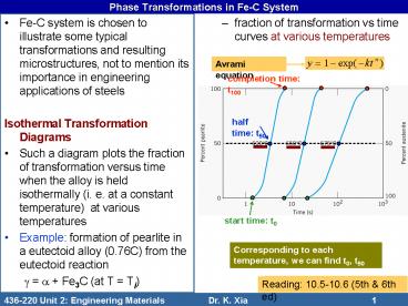
- Such a diagram plots the fraction of
transformation versus time when the alloy is held
isothermally (i. e. at a constant temperature)
at various temperatures - Example formation of pearlite in a eutectoid
alloy (0.76C) from the eutectoid reaction - g a Fe3C (at T Ti)
- fraction of transformation vs time curves at
various temperatures
Avrami equation
completion time t100
half time t50
start time t0
Corresponding to each temperature, we can find
t0, t50 and t100.
Reading 10.5-10.6 (5th 6th ed)
2
Phase Transformations in Fe-C System
- plot temperature versus log t0, t50 and t100,
respectively - connecting all the points for t0 the start
curve - connecting all the points for t50 the half
curve - connecting all the points for t100 the
completion curve - these curves are also called TTT curves or C
curves - the rate of transformation is the fastest at an
intermediate temperature (the nose)
no reaction above Te
675
t50 28 h at 720C
650
t50 lt 5 s at 600C
3
Phase Transformations in Fe-C System
due to high diffusion rate
ABCD a real heat treatment route
due to low diffusion rate
4
Phase Transformations in Fe-C System
Coarse pearlite
Micro-structures
Fine pearlite
5
Phase Transformations in Fe-C System
- Extended (down to 215C) TTT diagram for the
eutectoid steel - at T lt 540C, a new microstructure - bainite -
forms as a result of phase transformation - Bainite takes a needle or a plate shape and
consists of elongated cementite in a matrix of
ferrite
nose - fastest trans-formation
ferrite
pearlite
cementite
540C
bainite
austenite
6
Phase Transformations in Fe-C System
- Complete TTT diagram for the eutectoid steel
- when cooled so fast that no C diffusion is
possible, a new phase - martensite - forms (at
even lower temperatures) from the austenite phase - the martensite (M) transformation is
diffusionless, and thus takes virtully no time
(the amount of M depends on T only, NOT on time)
Above M(start), no M forms
At M(90), 90 of A transforms into M
7
Phase Transformations in Fe-C System
- martensite
- Fe forms a body-centred tetragonal (BCT) unit
cell - C atoms remain in the interstitial sites (no
formation of cementite) - a non-equilibrium phase (not present in the phase
diagram)
Dark phase martensite of needle shape Light
phase untransformed austenite
hard and brittle
further transfor-mation possible
Martensite (BCT)
Austenite (FCC)
c gt a
8
Phase Transformations in Fe-C System
- Example 10.1
- Fe-C of eutectoid composition
- starting microstructure g at 760C
- Find microstructures and percentages of each
microconstituent after the following heat
treatments - (a) rapid cooling to 350C, holding for 10000 s,
and quenching to RT - (b) rapid cooling to 250C, holding for 100 s,
and quenching to RT - (c) rapid cooling to 650C, holding for 20 s,
rapid cooling to 400C, holding for 1000 s, and
quenching to RT
no more transformation
A to P starts
50P
100A
50A
These phases and structures cannot be read from
the equilibrium phase diagram!!
A to B completes
A to B starts
A to B starts
100B
100A
50B
100A
100A
No M forms as the starting phase is B or P
A to M starts
50M
90M
9
Phase Transformations in Fe-C System
- Effect of composition
- C non-eutectoid compositions
- e. g. a hypereutectoid alloy (Co)
- proeutectoid cementite may appear
Co
T'
T'
A to C starts
A C coexist
Proeutectoid Fe3C
C
C
A to P completes
A to C completes A to P starts
A to C starts
10
Phase Transformations in Fe-C System
- other alloying elements
- shape and position of the starting, half and
completion lines may be different
proeutectoid ferrite
HW follow isothermal phase transformations of
alloy steel 4340 at 350, 550, 650 and 750C
4340 alloy steel Fe-0.4C-1.8Ni-0.7Mn-0.8Cr-0.2Si-
0.25Mo
Fe-0.76C
11
Phase Transformations in Fe-C System
- Continuous cooling transformation (CCT) diagrams
- In practice, the cooling is often continuously
carried out at a certain rate to room
temperature, rather than rapid cooling to a
certain temperature and holding at the
temperature for a period of time when the
isothermal transformation diagrams are
applicable. - For continuous cooling, the transformation
diagrams are different various curves are
usually shifted to lower temperatures and longer
times. Also, some phases may not appear at all.
isothermal holding
continuous cooling
12
Phase Transformations in Fe-C System
- Example continuous cooling of a eutectoid steel
A to P starts
P
A
A to P finishes 100 P
A to P transfor-mation stops at line AB
A to P stops P remaining A
remaining A to M starts
A to M starts
Cooling rate determines what microstructures will
be present following heat treatment
P M
M
13
Phase Transformations in Fe-C System
- Things can certainly get much more complicated
with alloying, but the diagram can be read in the
same way.
4340 alloy steel
HW Try to reach the final microstructures
following cooling at different rates

