MINERnA - PowerPoint PPT Presentation
1 / 12
Title:
MINERnA
Description:
What we need to do next. DAQ and Slow Control. What we need. When we need it ... head of the Fermilab Electrical Safety Subcommittee so we are in very good shape ... – PowerPoint PPT presentation
Number of Views:23
Avg rating:3.0/5.0
Title: MINERnA
1
MINERnA
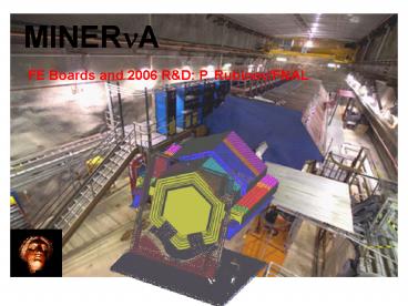
FE Boards and 2006 RD P. Rubinov/FNAL
2
Electronics in MINER?A
- Front-end Electronics
- What we know
- What we need to do next
- DAQ and Slow Control
- What we need
- When we need it
- Power and Rack Protection
- a few words on Low Voltage
- grounding
FE Board
3
Front End board
- 16ch proto FE boards have been used so far
(designed to interface to Alner box) - Seem to work ok.
- Tested LVDS chain scheme (work done by C Gingu)
4
LVDS chain
- LVDS chain implemented by C. Gingu.
- Learn about reliability, latency, phase noise
- These set maximum chain length
- E.g. latency is 113ns per board so need spill
signal at least 113ns121.4ns/foot 1.4uS
before spill
5
CW generator
- Recently assembled prototypes
- 22 stage Cockroft-Walton fed by a resonant
converter - Seem to work ok
- Needs to be tested with PMT tube
6
Next step for FE
- 64ch board designed for Minerva PMT box
- Pick TriP or TriP-t
- Implement bigger FPGA
- Integrate CW generator circuitry
- Implement realistic LV distribution (worry more
about power dissipation)
7
Next step for FE
- Our current plan is
- HV generator is split in two partly in the
base, partly on the FE. - The base carries the actual diode ladder.
- It is designed to fit into the Minerva PMT
box(now things are becoming coupled!) - Design of the base is done and out for quotes.
- I think we can use a butchered up HV prototype to
drive this base. - Notice the LEMO- this connects to the last dynode
8
Next step for FE
9
DAQ
- We need CROC design which will allow for a
realistic readout and control of the next
generation prototype FE. - The CROC is
- 100 digital 6U VME module
- Less complicated than FE but equally important.
- We need it
- to test a full length chain
- have sufficient DAQ bandwidth for PMT testing
10
LV and Grounding
- Stan Orr (Fermilab engineer) has been asked to
help us out with these issues. - Stan is head of the Fermilab Electrical Safety
Subcommittee so we are in very good shape here. - LV distribution philosophy is
- Distribute at 48V (50V is safety threshold) to
minimize current (smaller, simpler cable plant) - Use commercial, off the shelf equipment.
11
LV and Grounding
- Grounding philosophy
- Local reference for every PMT.
- One common safety ground.
- Important point
- Everyone should understand If it conducts, it
is part of the electronics.(no matter what the
WBS code is)
12
Conclusion
- In FY2006 we expect to have
- Second FE prototype, realistic for Minerva
- Qty 20
- PMT base which works with M64 and our boxes
- Qty enough for PMT testing, 40
- CROC module
- Qty 4, at least one fully working needed for
PMT testing.


