Intro/outline - PowerPoint PPT Presentation
1 / 12
Title:
Intro/outline
Description:
University of Washington, Seattle WA. Devlin R. Baker ... Ions Impinging Radially Inward Do Not Satisfy the Center of Mass Frame Reaction Rates ... – PowerPoint PPT presentation
Number of Views:39
Avg rating:3.0/5.0
Title: Intro/outline
1
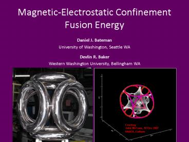
Magnetic-Electrostatic Confinement Fusion Energy
Daniel J. Bateman University of Washington,
Seattle WA Devlin R. Baker Western Washington
University, Bellingham WA
2
Outline
- Primary Fusion Energy Research
- Magnetic Confinement
- Inertial Confinement
- Electrostatic Confinement
- Polywell System (Electrons Injected)
- Magnetic-Electrostatic Confinement
- Conclusions
3
Magnetic Confinement
Construction scheduled to begin in 2009 First
plasma scheduled for 2016 Goal Produce 400-500MW
output from 40MW input Ggt10 Will not produce
useable power
ITER - 1010
4
Inertial Confinement
Estimated to be completed in 2009 First ignition
tests scheduled for 2010 Will not produce useable
power
- National Ignition Facility (NIF) - 109
5
Electrostatic Confinement
- University of Wisconsin Madison
- Univeristy of Illinois at Urbana-Champaign
- Hobbyists, Science Fair, etc.
IEC - from 103 Steady State Not for energy
production
6
How Does Electrostatic Confinement Work?
If inner grid is positive electron
acceleration device (EXL) If inner grid is
negative ion acceleration device (IXL)
First paper (1959 Elmore et al.) was on EXL
First experiments (Hirsch Farnsworth) were
on EXL EXL devices create negative
electrostatic potential well which accelerate
ions to the center of the sphere Grid
losses prevent net energy gain Increasing grid
transparency decreases structural integrity
Electron Acceleration (EXL) Device
7
Ions Impinging Radially Inward Do Not Satisfy the
Center of Mass Frame Reaction Rates
Reaction rate
8
Magnetic-Electrostatic Confinement The Polywell
Device Uses a Magnetic Grid
Electromagnets become inner grid both the
outer shells and the inner coils are charged
to high potential (15kV min) Shape of
electromagnets must be conformal to magnetic
field Box coils were used from mid 1990s to
2004 with poor results Coil spacing to provide
point cusp magnetic field at each corner
9
Background of the Polywell Device
Proposed by Robert W. Bussard in 1985
Analysis by Nicholas A. Krall with first paper
published 1992 Krall Rosenberg paper 1992
shows that ion-ion Maxwellianization in the
edge region helps to maintain primarily radial
ion flow in the interior
10
Collisionality
Three distinct regions exist for both electrons
and ions
Electrons
Central region Electrons at lowest
energy, Maxwellian Approximately constant
charge density Wiffleball Primarily
radial velocity distribution Inverse-square
of radius density dependence High B
gradient boundary reflection Edge
Electrons at high energy Escaping electrons
recirculate through cusp current Core
Ions at highest energy, non-Maxwellian
Extremely low time-in-region Bulk
Primarily radial velocity distribution, minimal
collisions Edge Ions at lowest
energy Large time-in-region, high
collisionality
Ions
11
Conclusions Inertial-electrostatic
confinement is an effective means of initiating
and sustaining nuclear fusion reactions. Grid
losses prevent net energy gain. MHD stable
polyhedral magnetic grid reduces grid
losses provides additional electron
confinement. Ions introduced near system radius
begin with radial oscillations in the well.
Collisional effects in must be considered within
distinct regions. Edge collisions dominate
interior collisions, which help to maintain
primarily radial flow
12
Questions?


